SATEC PM180 Operation Manual User Manual
Page 69
Chapter 7 Programming the PM180
Configuring Digital Inputs
PM180 Substation Automation Unit
67
in the order of connection when the device is powered up. For example, if two DI
modules are connected to the device, the digital inputs DI1-DI16 belong to the first
module, and DI17-DI32 - to the following module. If you insert an I/O module into
another slot position and do not change its order, then all digital inputs on the module
retain their I/O numbers.
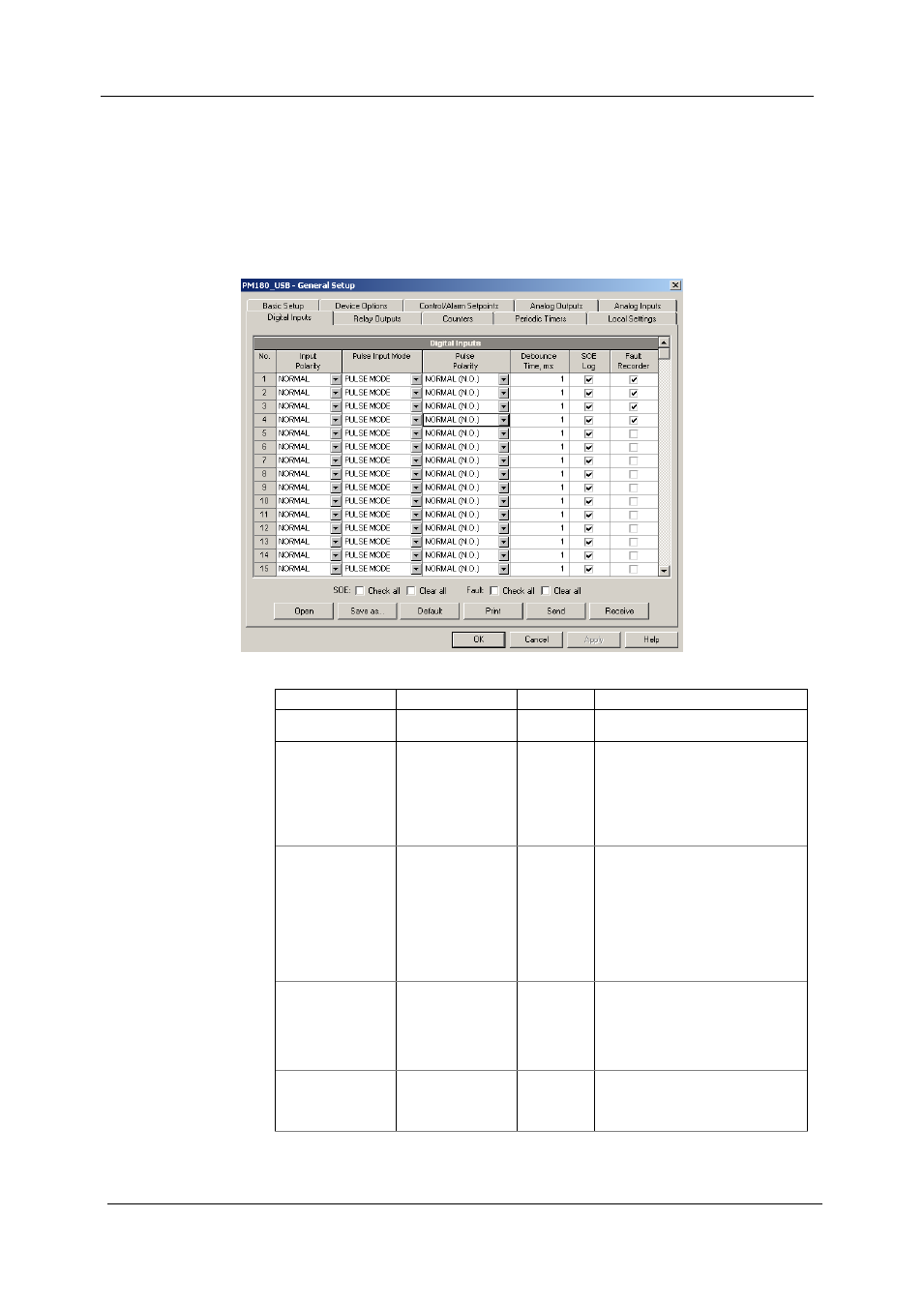
To configure the digital inputs in your device, select the device site from the list box
on the PAS toolbar, select General Setup from the Meter Setup menu, and then click
on the Digital Inputs tab. The digital inputs that are not present in your device are
designated as not available.
The available options are described in the following table:
Option
Range
Default
Description
Input Polarity
NORMAL,
INVERTING
NORMAL
Defines the input polarity state
Pulse Input Mode
PULSE MODE
KYZ MODE
PULSE
MODE
Defines the type of a pulse on the
input when it receives external
pulses. In pulse mode, either
leading, or trailing edge of the input
pulse is accepted. In KYZ mode,
both leading and trailing edges of the
input pulse are accepted.
Pulse polarity
NORMAL (N.O.)
INVERTING (N.C.)
NORMAL
Selects the active pulse edge that is
considered a pulse in pulse mode.
For normal polarity, the open to
closed transition is considered a
pulse. For inverting polarity, the
closed to open transition is
considered a pulse.
It has no meaning in KYZ mode
where both transitions are active.
Debounce time, ms 1-100 ms
1
The amount of time the state of the
digital input should not change
before being accepted as a new
state. Too low debounce time could
produce multiple events on the input
change.
SOE Log
Checked
Unchecked
Unchecked When the box is checked, either
transition on the digital input is
recorded to the Sequence-of-Events
log.