SATEC PM180 Operation Manual User Manual
Page 149
Chapter 14 Viewing Log Files
Viewing Waveforms
PM180 Substation Automation Unit
147
Viewing Phasor Diagrams
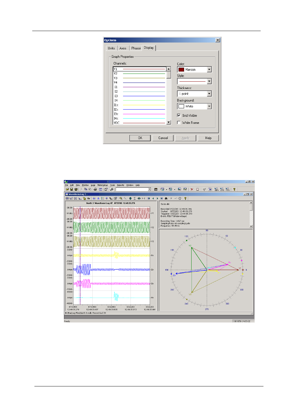
The phasor diagrams show you the relative magnitudes and angles of the three-
phase voltage and current fundamental component. All angles are shown relative to
the reference voltage channel.
PM180_USB
PAS V1.4 - [C:\Pas] Waveform Log 7
PM180_USB
PM180_USB
To change the reference channel, click on the waveform window with the right mouse
button, select “Options...”, click on the “Phasor” tab, check the channel you want to
make a reference channel, and then click “OK”.