Chapter 3 using the rdm, Connecting the rdm, Data display – SATEC PM180 Operation Manual User Manual
Page 28: Using the rdm
Chapter 3 Using the RDM
Connecting the RDM
26
PM180 Substation Automation Unit
Chapter 3 Using the RDM
Connecting the RDM
Connect the RDM to the PM180 COM3 port using the supplied cable as shown in the
PM180 Installation Manual. When the PM180 is powered, the RDM display lights up.
The COM3 and RDM communications settings must match one another. Both the
COM3 port and the RDM RS-485 port are factory preset to 19200 bps, 8-bits/no-
parity, device address 1, Modbus RTU protocol.
When the RDM fails to establish communications with the PM180, the RDM display
indicates a connection error as shown on the left picture. When this happens:
1. Check your connections
2. Check whether the PM180 is in the Service Mode
3. Check whether communications settings in the RDM match the
settings made for the COM3 port of the PM180. For information on
how to get the serial port settings in your PM180, see
in Chapter 4 “Using HyperTerminal”. If you want to
revise the RDM communications settings, press ENTER and follow
guidelines for the Display Setup menu (see
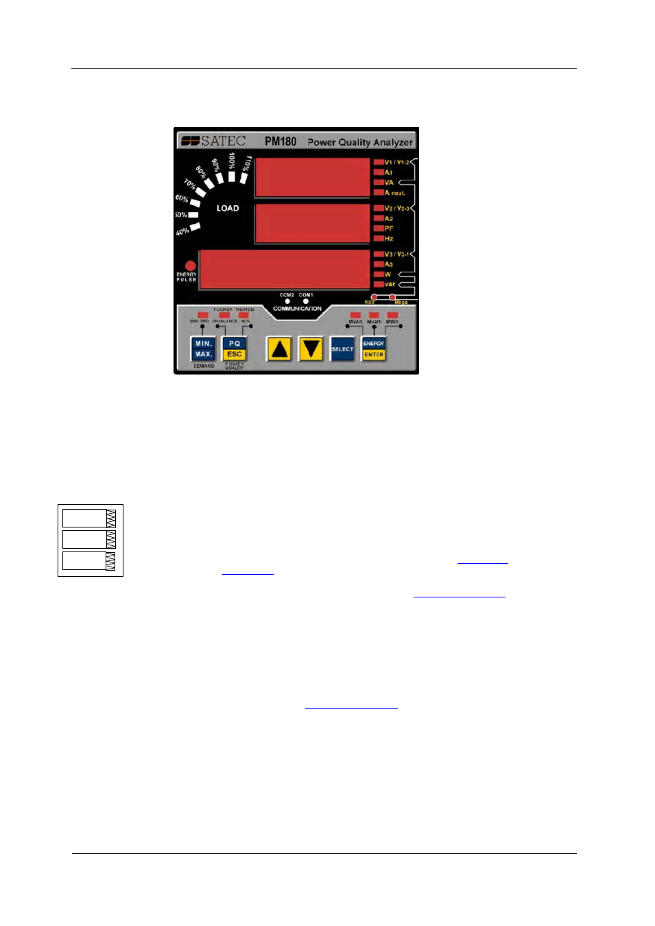
Data Display
The RDM has a simple interface that allows you to display numerous measurement
parameters in different display pages. The numeric LED display shows up to three
parameters at a time. Small round LEDs on the right and below the display indicate
displayed parameters and their measurement units.
The display is updated approximately once per second; you can adjust the update
rate via the Display Setup Menu (see
Measurement Units
Depending on the connection scheme of the PM180, the RDM can be ordered for
direct wiring or wiring via PTs. Measurement units for voltage and power depend on
the connection scheme of the device:
When direct wiring is used, voltages are displayed in volts
with one decimal place, and power in kilowatts with three
decimal places.
diSP
Con.Err.