Basic device setup – SATEC PM180 Operation Manual User Manual
Page 63
Chapter 7 Programming the PM180
Basic Device Setup
PM180 Substation Automation Unit
61
Basic Device Setup
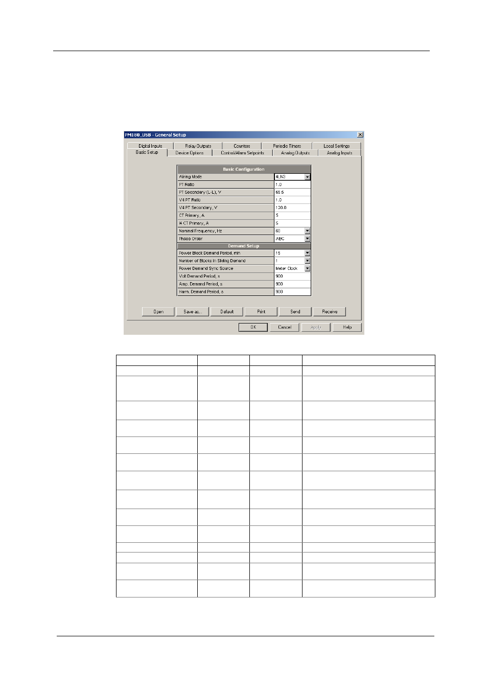
Before operating your device, define the basic information about your electrical
network.
To enter the setup dialog, select the device site from the list box on the PAS toolbar,
and then select General Setup from the Meter Setup menu.
The following table lists available device configuration options.
Option
Range
Default
Description
Basic Configuration
Wiring connection mode
(configuration)
See “Wiring
Connections”
below
4LN3
The wiring connection of the device
PT ratio
1
V1-V3 voltage inputs
1.0 - 6500.0
1.0
The phase potential transformer ratio
(primary to secondary ratio)
PT secondary (L-L), V
10-690 V
120
The phase potential transformer’s
secondary phase-to-phase voltage
V4 PT ratio
1
1.0 - 6500.0
1.0
The V4 potential transformer ratio (primary
to secondary ratio)
V4 PT secondary, V
10-690 V
120
The V4 potential transformer’s secondary
voltage
CT primary, A
I1-I3 current
2
inputs
1-10000 A
5
The primary rating of the phase current
transformer on standard (20A/10A) inputs
I4 CT primary, A
current
1-10000 A
5
The primary rating of the I4 current
transformer on standard (20A/10A) inputs
I4 CT secondary current
1, 5 A
5
The secondary rating of the I4 current
transformer on standard (20A/10A) inputs
Nominal frequency, Hz
50, 60 Hz
50 (60 for North
America)
The nominal power frequency
Phase order
ABC, CBA
ABC
The normal phase sequence
Demand Setup
Power Block demand
period, min
1, 2, 5, 10, 15,
20, 30, 60
15
The length of the demand period for power
demand calculations
Number of Blocks in
sliding window
1-15
1
The number of demand periods to be
averaged for sliding window demands