Metering, Rms measurements, Rms trace – SATEC PM180 Operation Manual User Manual
Page 20
Chapter 2 Device Description
Metering
18
PM180 Substation Automation Unit
release command. The remote release command also removes the local commands
that hold a latched relay in active state.
A remote operate command sent to a pulse or KYZ relay forces the relay to produce
a pulse or changes its state. A remote release command sent to a pulse or KYZ relay
has no effect since the operate command is cleared automatically for these relays.
Retentive Relays
Latched relays can be set to operate in retentive mode. Retentive mode affects the
behavior of the relay after loss of power.
After restoring power, all non-retentive relays are in inactive state until local
conditions are reevaluated. All active remote commands for non-retentive relays are
cleared.
Retentive relays retain their status after restoring power, and all active remote
commands that were issued before loss of power are still effective.
Critical Faults
When a critical error is detected by the device diagnostics, all relays are released
regardless of their operation mode, and all remote relay commands are removed.
Metering
RMS Measurements
All RMS quantities are based on 1/2-cycle true RMS measurements performed over
64 samples of the acquired waveforms. The 1/2-cycle quantities are values
(normally, RMS volts, RMS currents and unbalances) measured over one cycle and
updated each half cycle (IEC 61000-4-30). This allows fast response to power quality
and fault events.
RMS Trace
The PM180 handles a circular RMS trace buffer that stores the last forty 1/2-cycle
RMS, unbalance, zero-sequence, VDC and frequency readings. This allows the data
recorder to provide 1/2-cycle trending of up to 20 pre-fault cycles when it is triggered
from the Power Quality or Fault recorder.
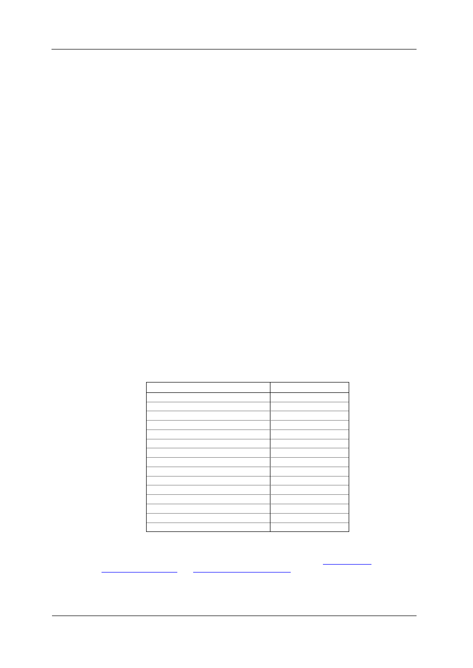
The following table lists parameters that are available for pre-fault tracing.
Parameter
Label
Phase-to-neutral volts
V1, V2, V3
Phase-to-phase volts
V12, V23, V31
Auxiliary volts
V4
Standard range currents
I1x, I2x, I3x, I4x
Standard range neutral current
Inx
Extended range currents
I1x, I2x, I3x, I4x
Extended range neutral current
Inx
Voltage zero sequence
V ZERO-SEQ
Standard range current zero sequence
I ZERO-SEQ
Extended range current zero sequence
Ix ZERO-SEQ
Voltage unbalance
V UNB%
Standard range current unbalance
I UNB%
Extended range current unbalance
Ix UNB%
DC voltage
VDC
Power frequency
Frequency
Data logs #13 (fault data trend) and Data logs #14 (PQ data trend) are internally
linked to the RMS trace buffer. The number of pre-fault cycles for data trending is
defined when configuring the Power Quality and Fault recorders. See