SATEC PM180 Operation Manual User Manual
Page 78
Chapter 7 Programming the PM180
Using Control Setpoints
76
PM180 Substation Automation Unit
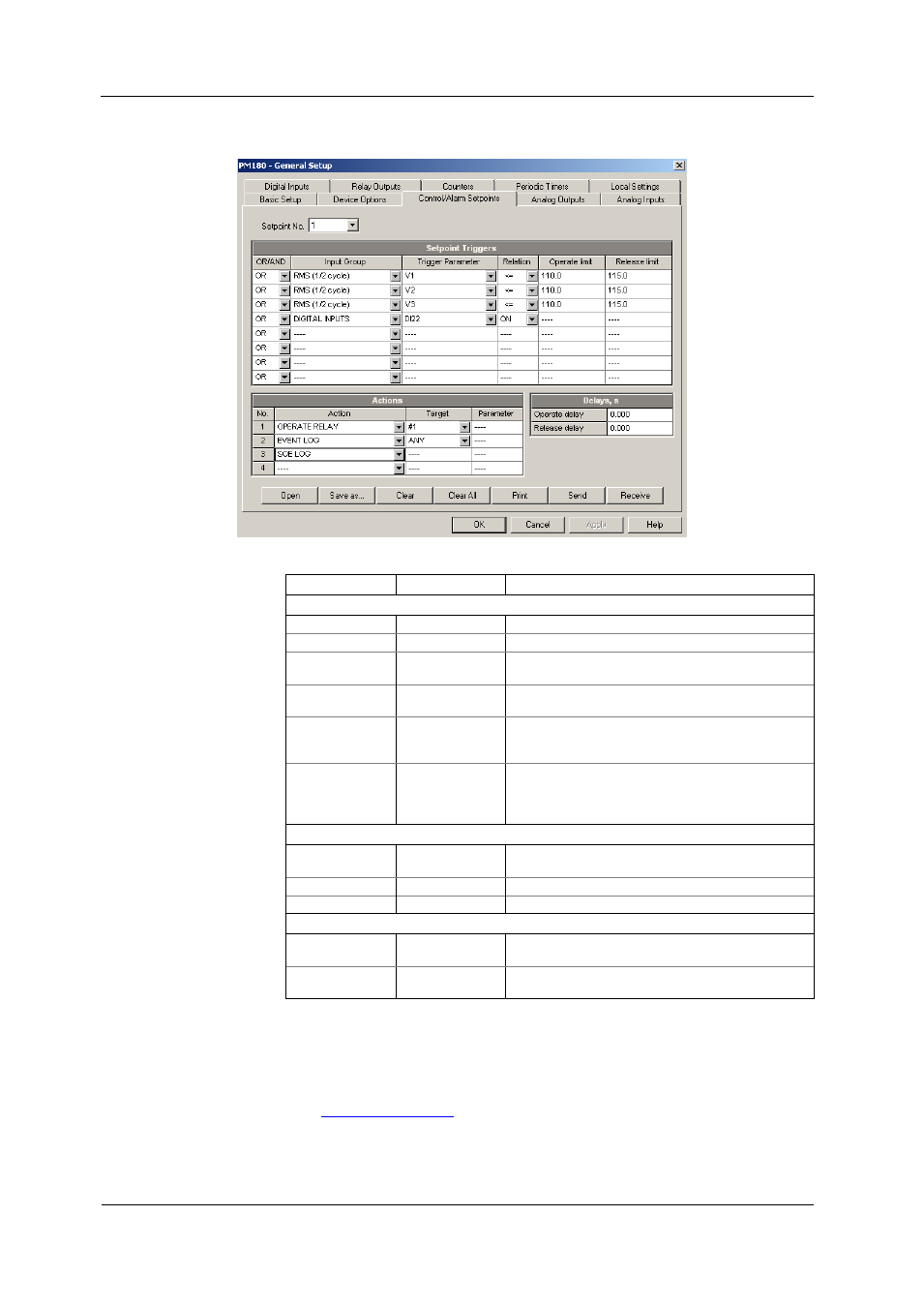
To program the setpoints, select General Setup from the Meter Setup menu, and
then click on the Control/Alarm Setpoints tab.
The available setpoint options are described in the following table:
Option
Format/Range Description
Setpoint Triggers
OR/AND
OR, AND
The logical operator for the trigger
Input group
The trigger parameter group (see Appendix C)
Trigger parameter
The trigger parameter that is used as an argument in
the logical expression (see Appendix C)
Relation
<=, >=, =, ON,
OFF, NEW, Delta
The relational operator used in the conditional
expression for the trigger
Operate limit
The threshold (in primary units) at which the
conditional expression would be evaluated to true. Not
applicable for digital triggers.
Release limit
The threshold (in primary units) at which the
conditional expression would be evaluated to false.
Defines the hysteresis for analog triggers. Not
applicable for digital triggers.
Setpoint Actions
Action
The action performed when the setpoint expression is
evaluated to true (see Appendix B)
Target
The optional action target
Parameter
The optional action argument (reserved)
Delays
Operate delay
0-10,000.000 sec The time delay before operation when the operate
conditions are fulfilled
Release delay
0-10,000.000 sec The time delay before release when the release
conditions are fulfilled
The logical controller provides very fast response to events. The scan time for all
setpoints is 1/2 cycle time (8 ms at 60Hz and 10 ms at 50 Hz).
Setpoint #1 is factory preset to provide standard periodic data logs on a 15-minute
time basis. It is linked to the device clock and runs Data logs #1 and #2 at 15-minute
boundaries of an hour.
The logical controller can be globally disabled or enabled through the Device Mode
Control dialog (see
in Chapter 11). It is enabled in your device
by default.