Wiring connections, Advanced device setup, In chapter 7) – SATEC SA300 ezPAC Operation Manual User Manual
Page 64: Sa300 substation automation unit
Chapter 7 Programming the SA300
Advanced Device Setup
64
SA300 Substation Automation Unit
Option Range
Default
Description
Nominal frequency
50, 60 Hz
50 (60 for North
America)
The nominal power frequency
Phase order
ABC, ACB
ABC
The normal phase sequence
1
PT Ratio is defined as a relation of the potential transformer’s primary voltage rating to its secondary
rating. For example, if your potential transformer’s primary rating is 14400V and the secondary rating is
120V, then the PT Ratio = 14400/120 = 120.
2
In the SA310 and SA320 models, the settings for the standard current inputs are the same as for the
extended current inputs. When you change setup for one of the current inputs, PAS automatically adjusts
settings for another input.
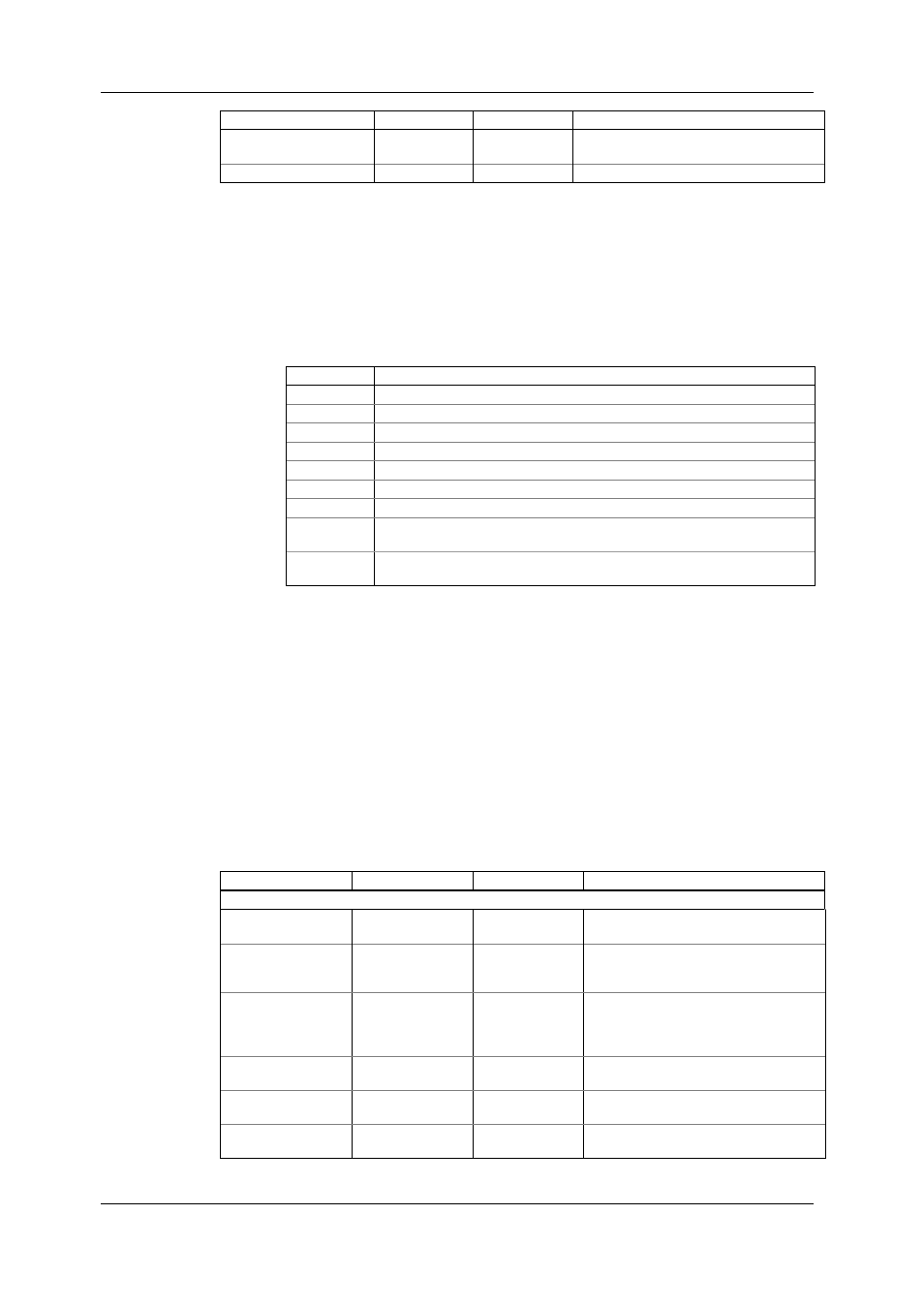
Wiring Connections
Available wiring modes are listed in the following table:
Wiring Mode
Description
3OP2
3-wire Open Delta using 2 CTs (2 element)
4LN3
4-wire Wye using 3 PTs (3 element), line-to-neutral voltage readings
3DIR2
3-wire Direct Connection using 2 CTs (2 element)
4LL3
4-wire Wye using 3 PTs (3 element), line-to-line voltage readings
3OP3
3-wire Open Delta using 3 CTs (2½ element)
3LN3
4-wire Wye using 2 PTs (2½ element), line-to-neutral voltage readings
3LL3
4-wire Wye using 2 PTs (2½ element), line-to-line voltage readings
3BLN3
3-wire Broken Delta using 2 PTs, 3 CTs (2½-element), line-to-neutral voltage
readings
3BLL3
3-wire Broken Delta using 2 PTs, 3 CTs (2½-element), line-to-line voltage
readings
In 4LN3, 3LN3 and 3BLN3 wiring modes, the voltage readings for min/max volts and
volt demands represent line-to-neutral voltages; otherwise, they will be line-to-line
voltages. The voltage waveforms and harmonics in 4LN3, 3LN3 and 3BLN3 wiring
modes represent line-to-neutral voltages; otherwise, they will show line-to-line
voltages.
Advanced Device Setup
This setup allows you to enable or disable optional calculations and change user-
selectable device options.
To enter the setup dialog, select the device site from the list box on the PAS toolbar,
select General Setup from the Meter Setup menu, and then click on the Advanced
Setup tab.
The following table lists available device options.
Option Range
Default
Description
Demand Setup
Power demand period 1, 2, 5, 10, 15, 20,
30, 60 min
15
The length of the demand period for
power demand calculations
The number of
demand periods in the
sliding window
1-15
1
The number of demand periods to be
averaged for sliding window demands
Power demand sync
source
Meter clock,
DI1-DI48 (digital
inputs 1-48)
Meter clock
The source input for synchronization of
the demand intervals. If a digital input is
specified as the source, a pulse front
denotes the start of the demand interval
Ampere demand
period
0 - 9000 sec
900
The length of the demand period for
ampere demand calculations
Volt demand period
0 - 9000 sec
900
The length of the demand period for volt
demand calculations
Harmonic demand
period
0 - 9000 sec
900
The length of the demand period for
harmonic demand calculations