Chapter 2 device description, Controls and indicators, Device controls – SATEC SA300 ezPAC Operation Manual User Manual
Page 12: Program-run key, Indicator leds
Chapter 2 Device Description
Controls and Indicators
12
SA300 Substation Automation Unit
Chapter 2 Device Description
Controls and Indicators
Device Controls
The SA300 is entirely controlled either from the remote display module (RDM or
RGM), or by using the supplemental PAS power analysis software package. The unit
has no controls except the PROGRAM-RUN key.
PROGRAM-RUN Key
The PROGRAM-RUN key is used to put the device into program mode for local
servicing and programming. For more information on the Program Mode, see
Opening a Terminal Session
in Chapter 4. For normal operations, the key must be left
in the RUN position.
:
Caution
Do not to put the PROGRAM-RUN key into the RESET position while the device is operating.
This causes immediate restart of the device and possible loss of information or incorrect
operation of the controlled external equipment.
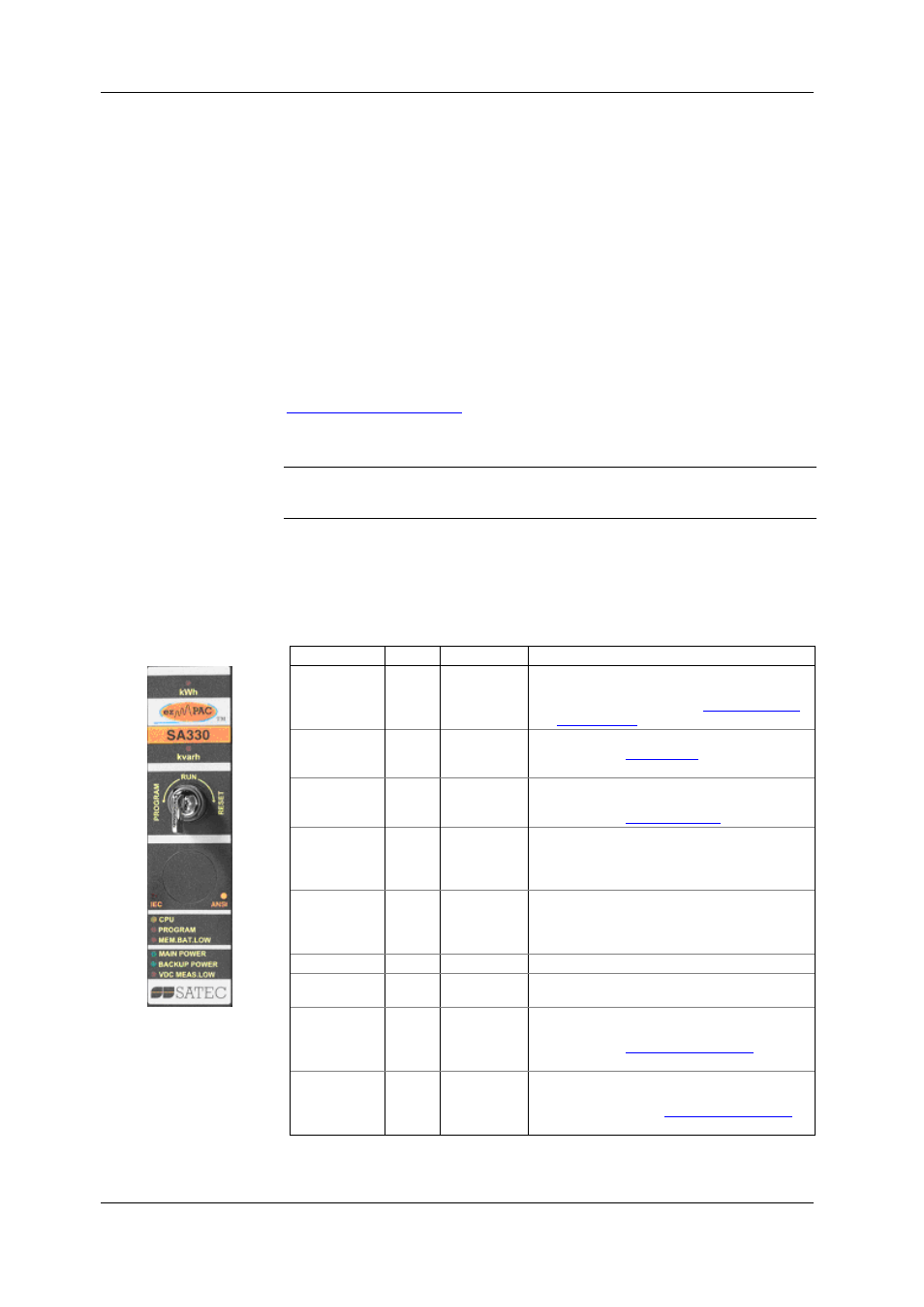
Indicator LEDs
The SA300 has six status indicator LEDs that show present device operation status
and give diagnostics indication; two energy pulsing LEDs that output kWh/kvarh
pulses; and twelve port status LEDs that show present ports status and
communications activity.
LED Name
Color
Status
Description
CPU Yellow
Flashing
1 sec On,
1 sec Off
Device operational and is functioning normally.
The COM1 RS-232 service port is available for
common communications. See
below.
Flashing
2 flashes,
1 sec Off
Device is in the Service Mode and is not
operational. See
below.
Flashing
3 flashes,
1 sec Off
A critical error has occurred - the device is not
operational. Device servicing is required. For more
information, see
below.
PROGRAM
Red
On
The PROGRAM-RUN key is in PROGRAM position.
The device is either in the Program Mode, or in
the Service Mode if the CPU LED is flashing 3
times.
MEM. BAT.
LOW
Red
On
The memory backup battery is near the end of its
operational life and should be replaced. See the
SA300 Installation Manual for instructions on
replacing the memory battery.
MAIN POWER
Green
On
Voltage is supplied to the main power supply unit.
BACKUP
POWER
Green
On
Voltage is delivered to the backup power supply
unit.
VDC MEAS.
LOW
Red
On
The station battery voltage is below the user-
programmed alarm threshold. For more
information, see
Chapter 7.
kWh/kvarh
Red
Flash at user-
programmed
rate
The device measures imported (consumed) active
and reactive energy. For information on defining
the LED pulse rate, see
Chapter 7.