Demand setup menu, Dnd 15 p.dp – SATEC SA300 ezPAC Operation Manual User Manual
Page 38
Chapter 3 Using the RDM
Configuring the SA300
38
SA300 Substation Automation Unit
Available wiring modes are listed in the following table.
Wiring Mode
Description
3OP2
3-wire Open Delta using 2 CTs (2 element)
4Ln3
4-wire Wye using 3 PTs (3 element), line-to-neutral voltage readings
3dir2
3-wire Direct Connection using 2 CTs (2 element)
4LL3
4-wire Wye using 3 PTs (3 element), line-to-line voltage readings
3OP3
3-wire Open Delta using 3 CTs (2½ element)
3Ln3
4-wire Wye using 2 PTs (2½ element), line-to-neutral voltage readings
3LL3
4-wire Wye using 2 PTs (2½ element), line-to-line voltage readings
3bLn3
3-wire Broken Delta using 2 PTs, 3 CTs (2½-element), line-to-neutral voltage readings
3bLn3
3-wire Broken Delta using 2 PTs, 3 CTs (2½-element), line-to-line voltage readings
To select a setup option:
1. Press SELECT to activate the middle window.
2. Use the Up/Down arrow keys to scroll to the desired option.
To change the display option:
1. Press SELECT to activate the lower window.
2. Use the Up/Down arrow keys to set the desired option.
3. Press ENTER to confirm your changes and to store your new
setting, or press ESC to discard changes.
To exit the menu:
From the middle window, press ESC or ENTER.
:
Notes
1. Always specify the wiring mode and transformer ratings prior to setting up setpoints and
triggers for the fault and power quality recorders.
2. The maximum value for the product of the phase CT primary current and PT ration is
10,000,000. If the product is greater, the powers and power factors are zeroed.
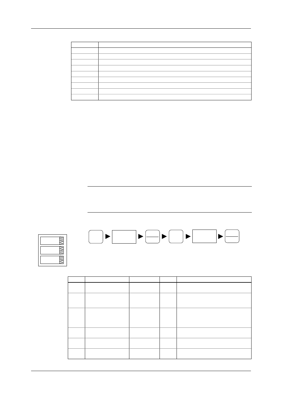
Demand Setup Menu
This menu allows you to configure the time parameters for calculating power,
ampere, volt and harmonic demands. To enter the Basic Setup menu, select “dnd”
from the menu list.
The following table lists available options, their default settings and ranges.
Label Option
Range
Default
Description
P.dP
Power demand period
1, 2, 5, 10, 15,
20, 30, 60 min
15
The length of the demand period for
power demand calculations
n.P.dP
The number of demand
periods in the sliding
window
1-15
1
The number of demand periods to be
averaged for sliding window demands
d.Snc.In Power demand sync
source
Clc (device
clock), di.In.1 -
di.In.48 (digital
input 1-48)
Clc
The source input for synchronization of
the demand intervals. If a digital input is
specified as the source, a pulse front
denotes the start of the demand interval
A.dP
Ampere demand period 0 - 9000 sec
900
The length of the demand period for
ampere demand calculations
U.dP
Volt demand period
0 - 9000 sec
900
The length of the demand period for volt
demand calculations
H.dP Harmonic
demand
period
0 - 9000 sec
900
The length of the demand period for
harmonic demand calculations
SELECT
ENERGY
ENTER
ENERGY
ENTER
CHG
S
dnd
dnd
15
P.dP