Cause & remedy, Drive plc, Appendix – Lenze Global Drive PLC Developer Studio User Manual
Page 92: 4 cause & remedy
8.5
System error messages
Drive PLC
Appendix
8−12
L
DrivePLC DE 6.0
8.5.4
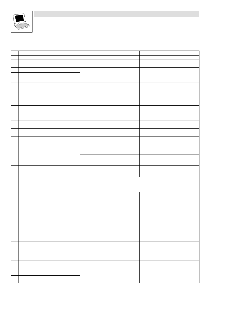
Cause & remedy
No.
Display
Meaning
Cause
Remedy
−−−
−−−
No error
−
−
061
CE0
Communication error
AIF module
óBasic unit
Interference during transfer of control commands
via automation interface (AIF)
Plug in automation module firmly, bolt down, if
necessary
062
CE1
CAN1_IN communication error
CANx_IN receives faulty data or communication
interrupted
·
Check wiring/cable
·
Check transmitter
·
If possible, increase monitoring time under
C0357/x
063
CE2
CAN2_IN communication error
064
CE3
CAN3_IN communication error
065
CE4
CAN BUS−OFF status
(too many faulty telegrams
received)
PLC has received too many faulty telegrams sent
via system bus and has disconnected itself from
the bus
·
Check wiring/cable
·
Check bus termination (if any)
·
Check screen contact of the cables
·
Check PE connection
·
Check bus load
·
Reduce baud rate (observe cable length)
066
CE5
CAN time−out
(gateway function)
For remote parameterisation via system bus
(C0370):
·
Slave does not respond
·
Communication monitoring time exceeded
·
Check system bus wiring/cable
·
Check system bus configuration
070
U15
Undervoltage of internal 15 V
voltage supply
Check voltage supply for Drive PLC
071
CCR
Internal error
The program sequence of the processor was
interfered
·
Shield control and motor cables as necessary
·
Check PE wiring and PE connections
072
PR1
Check sum error
in parameter set 1
CAUTION:
Lenze setting is loaded
automatically!
·
Error while loading a parameter set
·
Interruption of parameter set transfer via
keypad (e.g. by disconnection of the keypad)
·
Set the desired parameters and save them
under C0003
·
For PR0 the supply voltage must be switched
off additionally
·
Check use of pointers
The saved parameters do not match the loaded
software version
Before an error can be acknowledged, the
parameter set must be manually saved under
C0003
074
PEr
Program error
Error detected in program
·
Check use of pointers
·
Send controller with parameter set and PLC
program (on diskette) to Lenze
075
PR0
General error in parameter sets
CAUTION:
Lenze setting is loaded
automatically!
See Cause & Remedy, no. 072 (PR1)
076
PR5
Error while saving parameters
Error while saving parameters in the fail−safe
memory area
Contact Lenze
079
PI
Error during
parameter initialisation
·
Error detected during parameter set transfer
between two controllers
·
Parameter set does not match the PLC or
controller (e.g. data transfer from a
high−performance controller to a
lower−performance controller)
·
Correct the parameter set
·
Check code initialisation values
080
PR6
Too many user codes
Reduce the number of user codes
x09
EEr
External monitoring activated
via DCTRL
A digital signal assigned to the TRIP−SET function
has been activated (system block DCTRL is
integrated as of software version V8.0)
·
Check external encoder
·
Deactivate monitoring (C0581 = 3)
105
H05
Internal error (memory)
Contact Lenze
108
H08
Extension board error
Extension board not connected correctly
·
Connect extension board properly
·
Check connection plug EB
óPLC
Extension board is not supported by PLC program
·
Adapt PLC program to extension board
·
Use extension board which is supported by PLC
program.
122
CE11
Communication error
FIF−CAN1_IN
FIF−CANx_IN receives faulty data or
communication interrupted
·
Check wiring/cable
·
Check transmitter
·
If possible, increase monitoring time under
C2457/x
123
CE12
Communication error
FIF−CAN2_IN
124
CE13
Communication error
FIF−CAN3_IN