Analog_io_fif (node number 201), Drive plc, 1 analog_io_fif (node number 201) – Lenze Global Drive PLC Developer Studio User Manual
Page 54: System blocks − fif standard−i/o
3.1
ANALOG_IO_FIF (node number 201)
Drive PLC
System blocks − FIF Standard−I/O
3−2
L
DrivePLC DE 6.0
3.1
ANALOG_IO_FIF (node number 201)
3.1.1
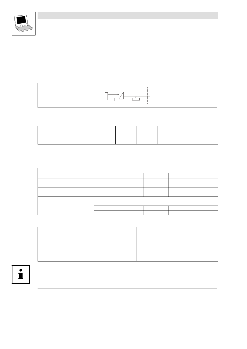
Inputs_ANALOG_FIF (analog input, "Standard I/O" FIF module)
This SB forms the interface for analog signals via terminal 8 of the Standard I/O FIF module as
setpoint input or actual value input.
8
AIN1_nIn_FIFSTDIO_a
Inputs_ANALOG_FIF
C0481
A
D
7
Fig. 3−1
Inputs_ANALOG_FIF
System variables
Variable
Data type
Signal type
Address
Display
code
Display
format
Notes
AIN1_nIn_FIFSTDIO_a
Integer
analog
%IW201.0
C0481
dec [%]
Analog input 1
Standard I/O
Input signal setting
By suitable switch settings at the Standard I/O FIF module the following input signals can be
processed:
Input range
1)
for terminal 8
Switch setting
1
2
3
4
5
0 ... +5 V
OFF
OFF
ON
OFF
OFF
0 ... +10 V (Lenze setting)
OFF
OFF
ON
OFF
ON
−10 ... +10 V
ON
ON
OFF
OFF
OFF
0 ... +20 mA
OFF
OFF
ON
ON
OFF
1)
The selected input range is adjusted to the integer range (0 ... 16384) of the variable AIN1_nIn_FIFSTDIO_a.
Example: selected input range = 0 ... +10 V
Input signal (terminal 8)
0 V
+ 5 V
+ 10 V
AIN1_nIn_FIFSTDIO_a
0
8192
16384
Electrical data of the input terminals:
Terminal
Use
level
Data
8
Analog input 1
0 ... +5 V
0 ... +10 V
−10 ... +10 V
0 ... +20 mA
Resolution:
Linearity error:
Temperature error:
Input resistance:
10 bit
±0.5 %
±0.3 % (0 ... 60 °C)
> 50 k
W (voltage signal)
250
W (current signal)
7
GND1, reference potential
for analog signals
−
−
Tip!
Detailed information about the terminal assignment for the Standard I/O FIF module can be found
in the corresponding Mounting Instructions!