Outputs_aif2, Drive plc, System blocks – Lenze Global Drive PLC Developer Studio User Manual
Page 25: 2 outputs_aif2, 3 aif2_io_automationinterface (node number 42)
Drive PLC
System blocks
2.3
AIF2_IO_AutomationInterface (node number 42)
2−11
L
DrivePLC DE 6.0
2.3.2
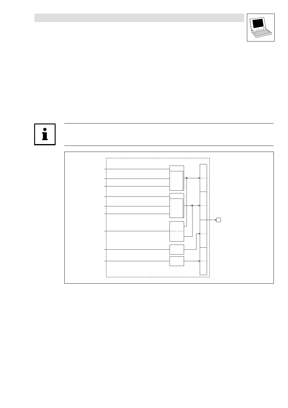
Outputs_AIF2
This SB is used as an interface for output signals (e.g. setpoints/actual values) to attached fieldbus
modules (e.g. INTERBUS, PROFIBUS−DP).
·
The process image is
– created in the cyclic task in a fixed time interval of 10 ms.
– created in an interval task within the time set for this task.
– read at the beginning of the task and written at its end.
Tip!
Please observe the Operating Instructions for the attached fieldbus module.
Outputs_AIF2
Automation
Interface
...
Byte
1
Byte
2
Byte
3
Byte
4
Byte
5
Byte
6
Byte
7
Byte
8
...
16 Bit
LowWord
16 Bit
HighWord
16 Bit
16 binary
signals
16 Bit
16 binary
signals
AIF2_nOutW2_a
AIF2_nOutW1_a
AIF2_bFDO0_b
AIF2_bFDO15_b
AIF2_bFDO16_b
AIF2_bFDO31_b
16 Bit
16 Bit
AIF2_nOutW4_a
AIF2_dnOutD1_p
AIF2_nOutW3_a
Fig. 2−5
Outputs_AIF2
- ESMD smd tmd remote keypad (4 pages)
- EPM Programmer EEPM1RA (114 pages)
- ESMDC (36 pages)
- SMD Frequency Inverter 0.37kW-22kW (116 pages)
- SMD Frequency Inverter: Basic I/O with CANopen 0.25kW-4.0kW (36 pages)
- SMD 0-25kW-4-0kW (112 pages)
- smd Series Drives (32 pages)
- ESV SMV remote keypad H0 (2 pages)
- ESV SMV remote keypad H1 (2 pages)
- SV SMV additional I-O module (14 pages)
- EEPM1RA EPM (26 pages)
- SMVector RS-485 LECOM (29 pages)
- E84AYM10S (4 pages)
- E84AYCET EtherCAT MCI module (109 pages)
- EZAMBKBM (6 pages)
- E84AYCEC (89 pages)
- ERBPxxxRxxxx Brake resistor 200W-300W (134 pages)
- E84AYCPM (115 pages)
- E84AYCEO (165 pages)
- E84AYCER (94 pages)
- E84AVSCx 8400 StateLine C (76 pages)
- EZVxxxx-000 Power supply unit AC 230V 5A-20A (62 pages)
- E84AYCIB (75 pages)
- E82ZWBRB (48 pages)
- EZVxx00−001 Power supply unit AC 400V 5A-20A (64 pages)
- E82ZWBRE (64 pages)
- EZAEBK1001 (94 pages)
- E94AYAE SM301 (134 pages)
- E94AYAE SM301 (74 pages)
- E94AYAE SM301 (140 pages)
- E94AZPS (114 pages)
- E94AYCIB (78 pages)
- E94AYCIB (124 pages)
- E94AZEX100 (84 pages)
- EZS3-xxxA200 Sinusoidal filter 115-150A (44 pages)
- E94AZHA0051 (104 pages)
- E94AZCDM030 (72 pages)
- EZS3-xxxA200 Sinusoidal filter 180-480A (74 pages)
- E94AYCCA (188 pages)
- E94AYCCA (114 pages)
- E94AZHB0101 (104 pages)
- E94AYCPM (114 pages)
- E94AYCPM (125 pages)
- E94AYCET (140 pages)
- E94AYCET (103 pages)