Drive plc, Appendix, 6 code table – Lenze Global Drive PLC Developer Studio User Manual
Page 110
8.6
Code table
Drive PLC
Appendix
8−30
L
DrivePLC DE 6.0
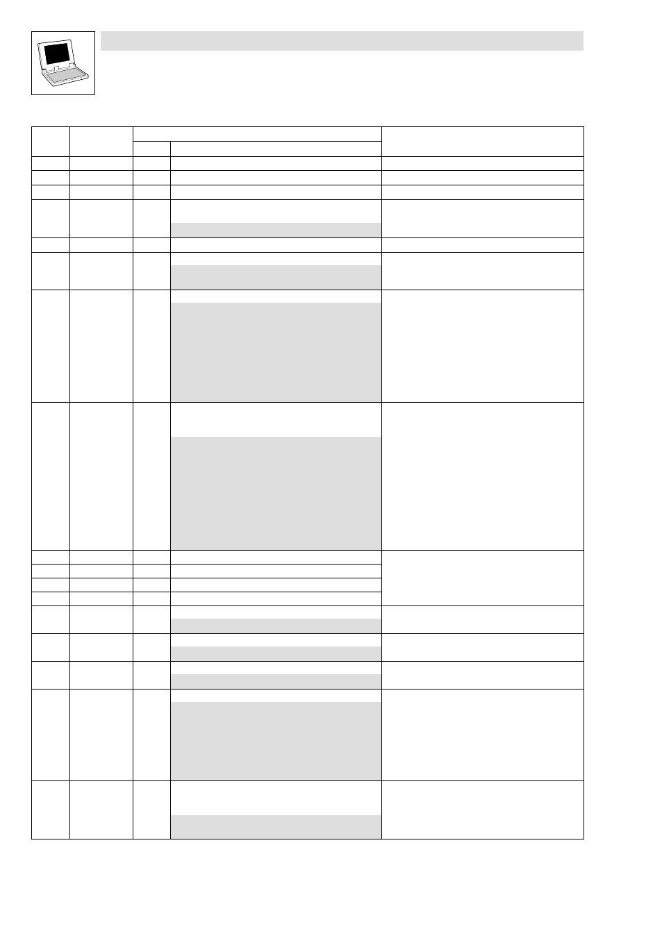
Code
Info
Possible settings
LCD
Code
Info
Selection
Lenze
LCD
C2111 GDC Id
g
Compilation time/date of PLC program
C2113 PLC Prog Name
g
Name of the PLC program
C2115 T−Fct credit
g
Technology units
C2116 CreditPinCode
0
PIN code for enabling technology units in case of servicing
(please contact Lenze)
0
{1}
4294967295
C2117 Full credit
g
Service code
C2118 ParWriteChan.
0
CAN object for L_ParRead and L_ParWrite
0
PDO channel (CAN1_IO ... CAN3_IO)
1
SDO2 channel
C2120 AIF: Control
AIF command
0
No command
1
Read CAN codes + reinitialisation
2
Read XCAN codes
10
Read XCAN C2356/1..4
11
Read XCAN C2357
12
Read XCAN C2375
13
Read XCAN C2376 ... C2378
14
Read XCAN C2382
15
Not assigned
C2121 AIF: state
g
AIF−CAN: Status
·
Detailed information can be found in the description for
the corresponding fieldbus module.
0
{dec}
255
Decimal value is bit−coded:
Bit 0
XCAN1_IN monitoring time
Bit 1
XCAN2_IN monitoring time
Bit 2
XCAN3_IN monitoring time
Bit 3
XCAN bus−off
Bit 4
XCAN operational
Bit 5
XCAN pre−operational
Bit 6
XCAN warning
Bit 7
Internally assigned
C2130 FileNameAddDa
g
Symbolic data name
Information about the additional data that were transferred
together with the PLC program to the PLC.
·
More detailed information can be found in chapter
8.3.2, "Downloading data".
^ 8−4
C2131 Type AddData
g
Data type
C2132 VersionAddData
g
Data version
C2133 TimeStamp
g
Time stamp of data
C2327 XCANGuardTime
0
Guard time
0
{1 ms}
65535
C2328 XCAN LT Fact.
0
Lifetime factor
0
{1}
255
C2350 XCAN address
1
AIF−CAN: Node address
1
{1}
63
C2351 XCAN baudrate
0
AIF−CAN: Baud rate
0
500 kbit/s
1
250 kbit/s
2
125 kbit/s
3
50 kbit/s
4
1000 kbit/s
5
20 kbit/s
6
10 kbit/s
C2352 XCAN mst
0
AIF−CAN: Set−up quasi master
·
Device sends system bus boot−up and is thus the
"quasi" master
0
Boot−up not active
1
Boot−up active