Drive plc, Appendix, 6 code table – Lenze Global Drive PLC Developer Studio User Manual
Page 108
8.6
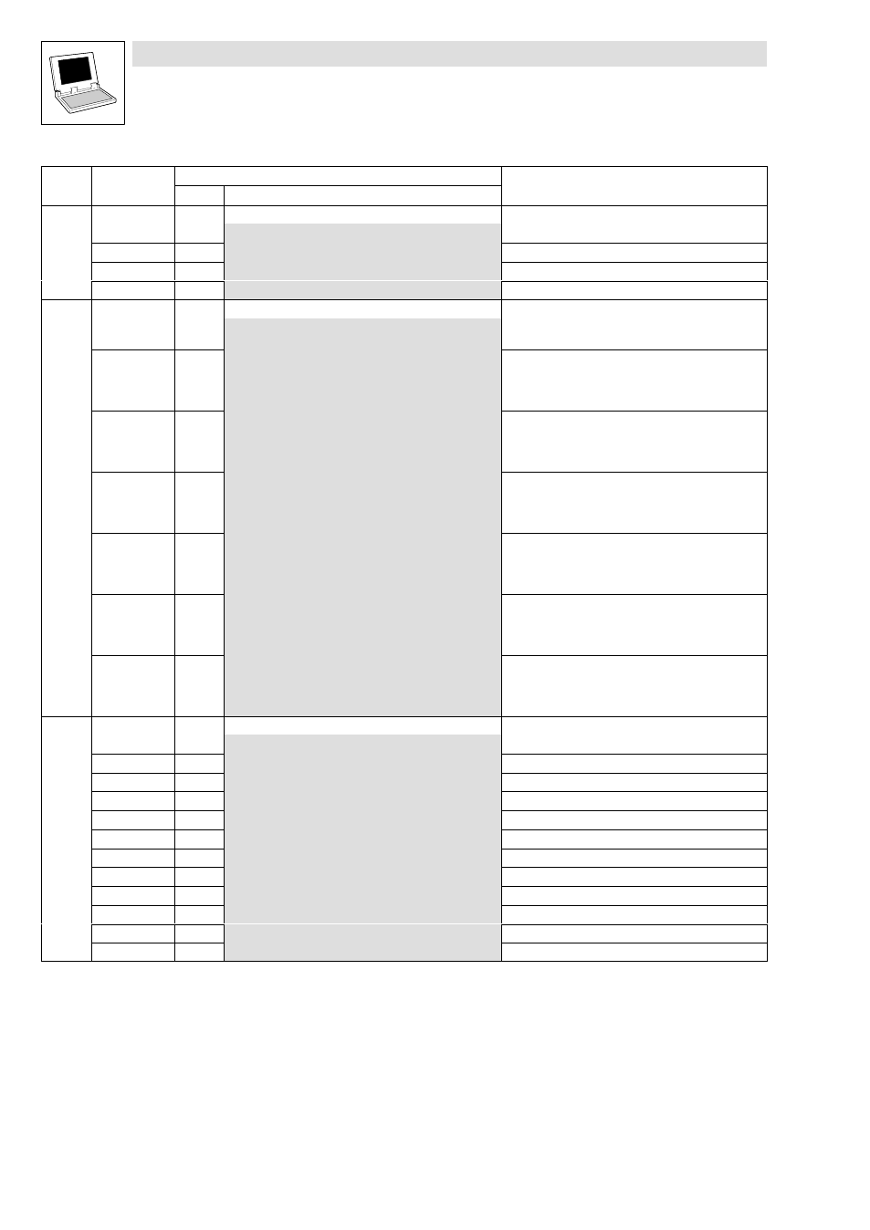
Code table
Drive PLC
Appendix
8−28
L
DrivePLC DE 6.0
Code
Info
Possible settings
LCD
Code
Info
Selection
Lenze
LCD
C0858 DIS: OUT.Wx
g
Automation interface (AIF): Process output words
−32768
{1 %}
32767
1
AIF1_OUT: Process data output word 2 (AIF1_nOutW1_a)
2
AIF1_OUT: Process data output word 3 (AIF1_nOutW2_a)
3
AIF1_OUT: Process data output word 4 (AIF1_nOutW3_a)
C0863 DIS: INx dig x
g
System bus: Process data input words
0000
{hex}
FFFF
Hexadecimal value is bit−coded:
1
Bit 00
CAN1_bInB0_b
Bit 01
CAN1_bInB1_b
...
Bit 15
CAN1_bInB15_b
CAN1_IN: Process data input word 1
2
Bit 00
CAN1_bInB16_b
Bit 01
CAN1_bInB17_b
...
Bit 15
CAN1_bInB31_b
CAN1_IN: Process data input word 2
3
Bit 00
CAN2_bInB0_b
Bit 01
CAN2_bInB1_b
...
Bit 15
CAN2_bInB15_b
CAN2_IN: Process data input word 1
4
Bit 00
CAN2_bInB16_b
Bit 01
CAN2_bInB17_b
...
Bit 15
CAN2_bInB31_b
CAN2_IN: Process data input word 2
5
Bit 00
CAN3_bInB0_b
Bit 01
CAN3_bInB1_b
...
Bit 15
CAN3_bInB15_b
CAN3_IN: Process data input word 1
6
Bit 00
CAN3_bInB16_b
Bit 01
CAN3_bInB17_b
...
Bit 15
CAN3_bInB31_b
CAN3_IN: Process data input word 2
C0866 DIS: INx.Wx
g
System bus: Process data input words
−32768
{1 %}
32767
1
CAN1_nInW1_a
2
CAN1_nInW2_a
3
CAN1_nInW3_a
4
CAN2_nInW1_a
5
CAN2_nInW2_a
6
CAN2_nInW3_a
7
CAN2_nInW4_a
8
CAN3_nInW1_a
9
CAN3_nInW2_a
10
CAN3_nInW3_a
11
CAN3_nInW4_a