Drive plc, Appendix – Lenze Global Drive PLC Developer Studio User Manual
Page 83
Drive PLC
Appendix
8.2
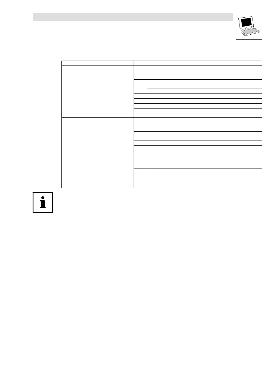
Extendability/networking
8−3
L
DrivePLC DE 6.0
System bus (CAN)
Interface
Available CAN objects
Integrated system bus interface
PDOs
CAN1_IN/CAN1_OUT
CAN2_IN/CAN2_OUT
CAN3_IN/CAN3_OUT
SDOs
SDO1 (parameter data channel 1)
SDO2 (parameter data channel 2)
L_ParRead/L_ParWrite functionality
Sync telegram
Synchronisation of the internal time basis by receiving sync telegrams
Free CAN objects
CanDSx driver for mapping indices to codes and for bus monitoring functions "Heartbeat"
and "Node Guarding" (see Manual "Function library LenzeCanDSxDrv.lib").
Automation interface (AIF)
with corresponding fieldbus module
(e.g. 2175)
PDOs
XCAN1_IN/XCAN1_OUT
XCAN2_IN/XCAN2_OUT
XCAN3_IN/XCAN3_OUT
SDOs
XSDO1 (parameter data channel 1)
XSDO2 (parameter data channel 2)
XSync telegram
AifParMap driver for mapping code accesses via AIF to other codes (see Manual "Function
library LenzeAifParMapDrv.lib").
Function interface (FIF)
with corresponding function module
(e.g. CAN−I/O system bus)
PDOs
FIF−CAN1_IN/FIF−CAN1_OUT
FIF−CAN2_IN/FIF−CAN2_OUT
FIF−CAN3_IN/FIF−CAN3_OUT
SDOs
FIF−SDO1 (parameter data channel 1)
FIF−SDO2 (parameter data channel 2)
L_ParRead/L_ParWrite functionality
Sync telegram
Tip!
Detailed information about the system bus (CAN) can be found in the Manual "System bus (CAN) for
Lenze PLCs"