Digital_io_eb2 (node number 3), Drive plc, System blocks − extension board 2 – Lenze Global Drive PLC Developer Studio User Manual
Page 66: 1 digital_io_eb2 (node number 3), System variables, Electrical data of the input terminals
6.1
DIGITAL_IO_EB2 (node number 3)
Drive PLC
System blocks − Extension Board 2
6−2
L
DrivePLC DE 6.0
6.1
DIGITAL_IO_EB2 (node number 3)
6.1.1
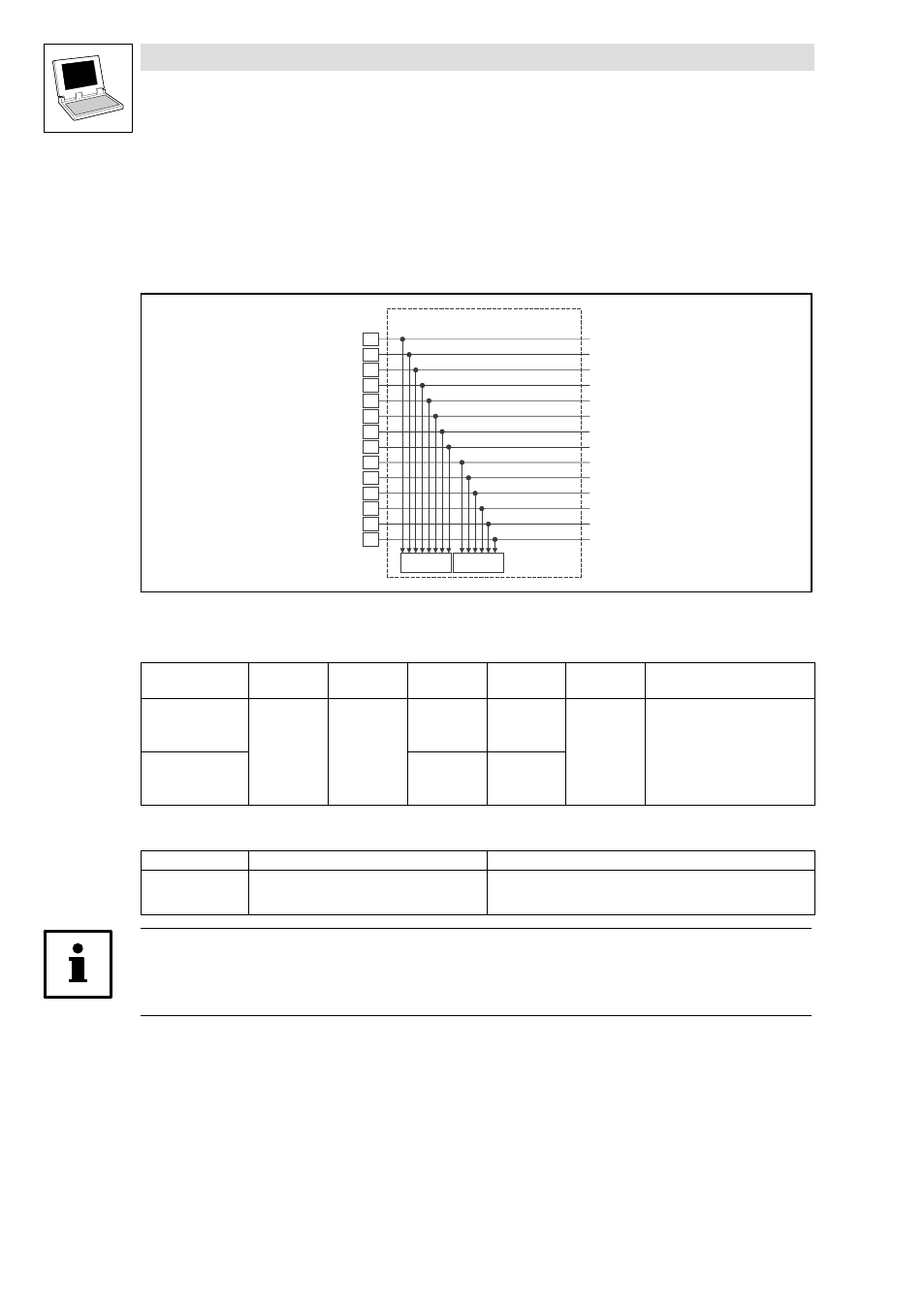
Inputs_DIGITAL_EB2 (digital inputs, extension board 2)
This SB reads the signals at terminals I9 ... I22 of the extension board 2 and conditions them.
I9
I10
DIGIN_bIn9_b
Inputs_DIGITAL_EB2
C0446/1
Bit 1 … Bit 8
I11
I12
I13
I14
DIGIN_bIn10_b
DIGIN_bIn11_b
DIGIN_bIn12_b
DIGIN_bIn13_b
DIGIN_bIn14_b
I15
I16
DIGIN_bIn15_b
I17
I18
I19
I21
I20
I22
DIGIN_bIn16_b
DIGIN_bIn17_b
DIGIN_bIn18_b
DIGIN_bIn19_b
DIGIN_bIn21_b
DIGIN_bIn20_b
DIGIN_bIn22_b
C0446/2
Bit 1 … Bit 6
Fig. 6−1
Inputs_DIGITAL_EB2
System variables
Variable
Data type
Signal type
Address
Display
code
Display
format
Notes
DIGIN_bIn9_b
Bool
binary
%IX3.0.0
C0446/1−bit1
bin
...
...
...
DIGIN_bIn16_b
%IX3.0.7
C0446/1−bit8
DIGIN_bIn17_b
%IX3.0.8
C0446/2−bit1
...
...
...
DIGIN_bIn22_b
%IX3.0.13
C0446/2−bit6
Electrical data of the input terminals
Terminal
Use
Data
I9
...
I22
freely assignable
LOW level:
HIGH level:
Input current:
0 ... +4 V
+13 ... +30 V
8 mA per input (at 24 V)
Tip!
Detailed information about the terminal assignment for the extension board 2 can be found in the
corresponding Mounting Instructions!