Drive plc, System blocks − extension board 3, 3 touch probe (tp) – Lenze Global Drive PLC Developer Studio User Manual
Page 76
7.3
DFIN_IO_DigitalFrequency (node number 21)
Drive PLC
System blocks − Extension Board 3
7−8
L
DrivePLC DE 6.0
Tip!
You can connect incremental encoders with HTL level that supply signals A and B only, to PIN 2 and
PIN 9. The inputs at PIN 3 and PIN 1 must then be connected to the supply voltage of the incremental
encoder.
The connection is as shown in the figures:
·
Use twisted pair cables and screened pair cables.
·
Connect the screen at both ends.
·
Do not change the cable cross−sections indicated.
7.3.1.3
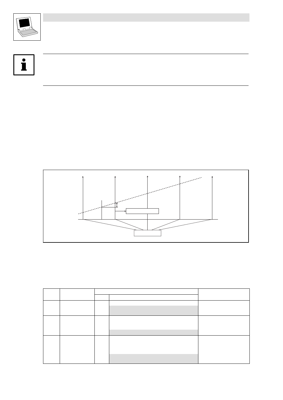
Touch probe (TP)
Process: The current angle value (encoder input value) is saved by a quick interrupt in the operating
system when a signal changes at the TP activating input (e.g. X3/I1).
DFIN_dnIncLastScan_p
TP
j
Fig. 7−8
Function chart of a TP
Time−equidistant start of an interval task
j Phase−angle signal
Touch probe configuration
Code
LCD
Possible settings
IMPORTANT
Lenze
Selection
C0428 DFIN TP sel.
0
Touch probe selection
0
Touch probe via zero pulse
1
Touch probe via digital input X3/I1
C0429 TP delay
0
Touch probe delay
·
Compensation of delay times
of TP signal source at X3/I1
−32767
{1 inc}
32767
C0431 DFIN TP EDGE
0
Touch probe activation
·
For touch probe via digital
input X3/I1
(C0428 = 1)
0
Activation with positive signal
1
Activation with negative signal