Digital_io_eb1 (node number 2), Drive plc, 1 digital_io_eb1 (node number 2) – Lenze Global Drive PLC Developer Studio User Manual
Page 62: System blocks − extension board 1
5.1
DIGITAL_IO_EB1 (node number 2)
Drive PLC
System blocks − Extension Board 1
5−2
L
DrivePLC DE 6.0
5.1
DIGITAL_IO_EB1 (node number 2)
5.1.1
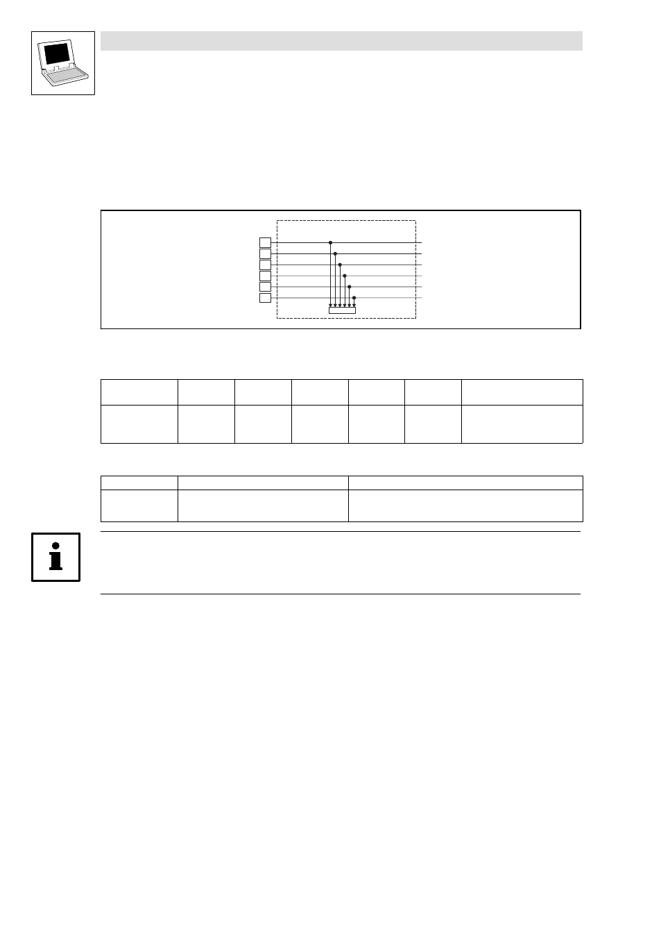
Inputs_DIGITAL_EB1 (digital inputs, extension board 1)
This SB reads the signals at terminals I9 ... I14 of the extension board 1 and conditions them.
I9
I10
DIGIN_bIn9_b
Inputs_DIGITAL_EB1
C0446/1
I11
I12
I13
I14
DIGIN_bIn10_b
DIGIN_bIn11_b
DIGIN_bIn12_b
DIGIN_bIn13_b
DIGIN_bIn14_b
Fig. 5−1
Inputs_DIGITAL_EB1
System variables
Variable
Data type
Signal type
Address
Display
code
Display
format
Notes
DIGIN_bIn9_b
Bool
binary
%IX2.0.0
C0446/1−bit1
bin
...
...
...
DIGIN_bIn14_b
%IX2.0.5
C0446/1−bit6
Electrical data of the input terminals
Terminal
Use
Data
I9
...
I14
freely assignable
LOW level:
HIGH level:
Input current:
0 ... +4 V
+13 ... +30 V
8 mA per input (at 24 V)
Tip!
Detailed information about the terminal assignment for the extension board 1 can be found in the
corresponding Mounting Instructions!
- ESMD smd tmd remote keypad (4 pages)
- EPM Programmer EEPM1RA (114 pages)
- ESMDC (36 pages)
- SMD Frequency Inverter 0.37kW-22kW (116 pages)
- SMD Frequency Inverter: Basic I/O with CANopen 0.25kW-4.0kW (36 pages)
- SMD 0-25kW-4-0kW (112 pages)
- smd Series Drives (32 pages)
- ESV SMV remote keypad H0 (2 pages)
- ESV SMV remote keypad H1 (2 pages)
- SV SMV additional I-O module (14 pages)
- EEPM1RA EPM (26 pages)
- SMVector RS-485 LECOM (29 pages)
- E84AYM10S (4 pages)
- E84AYCET EtherCAT MCI module (109 pages)
- EZAMBKBM (6 pages)
- E84AYCEC (89 pages)
- ERBPxxxRxxxx Brake resistor 200W-300W (134 pages)
- E84AYCPM (115 pages)
- E84AYCEO (165 pages)
- E84AYCER (94 pages)
- E84AVSCx 8400 StateLine C (76 pages)
- EZVxxxx-000 Power supply unit AC 230V 5A-20A (62 pages)
- E84AYCIB (75 pages)
- E82ZWBRB (48 pages)
- EZVxx00−001 Power supply unit AC 400V 5A-20A (64 pages)
- E82ZWBRE (64 pages)
- EZAEBK1001 (94 pages)
- E94AYAE SM301 (134 pages)
- E94AYAE SM301 (74 pages)
- E94AYAE SM301 (140 pages)
- E94AZPS (114 pages)
- E94AYCIB (78 pages)
- E94AYCIB (124 pages)
- E94AZEX100 (84 pages)
- EZS3-xxxA200 Sinusoidal filter 115-150A (44 pages)
- E94AZHA0051 (104 pages)
- E94AZCDM030 (72 pages)
- EZS3-xxxA200 Sinusoidal filter 180-480A (74 pages)
- E94AYCCA (188 pages)
- E94AYCCA (114 pages)
- E94AZHB0101 (104 pages)
- E94AYCPM (114 pages)
- E94AYCPM (125 pages)
- E94AYCET (140 pages)
- E94AYCET (103 pages)