Inputs_dctrl, Drive plc, System blocks – Lenze Global Drive PLC Developer Studio User Manual
Page 46: 1 inputs_dctrl
2.12
DCTRL_DriveControl (node number 121)
Drive PLC
System blocks
2−32
L
DrivePLC DE 6.0
2.12.1
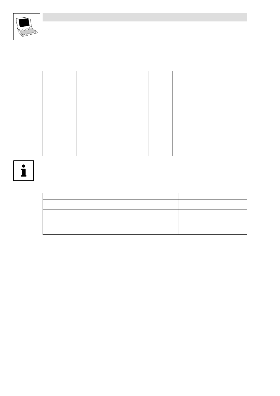
Inputs_DCTRL
System variables
Variable
Data type
Signal type
Address
Display
code
Display
format
Notes
DCTRL_bFail_b
Bool
binary
%IX121.0.0
−
−
Status word bit−coded
TRUE = Error active
DCTRL_bTrip_b
Bool
binary
%IX121.0.2
−
−
Status word bit−coded
TRUE = Error active (TRIP or FQSP
active)
DCTRL_bWarn_b
Bool
binary
%IX121.0.12
−
−
Status word bit−coded
TRUE = Warning active
DCTRL_bMeld_b
Bool
binary
%IX121.0.13
−
−
Status word bit−coded
TRUE = Message active
DCTRL_bExternalFault
_b
Bool
binary
%IX121.0.15
−
−
Status word bit−coded
TRUE = External error
DCTRL_wStat
WORD
−
%IW121.0
−
−
Status word with device status
(bit 8 ... 11, see below)
DCTRL_wFaultNumbe
r
WORD
−
%IW121.2
−
−
Error number from C0168
Tip!
Unlike ECS and SPLC, the binary signals of the SB DCTRL are on DCTRL_wStat!
Device status: Bits 8 ...11 of DCTRL_wStat show the DrivePLC status binary coded:
DCTRL_wStat.11
DCTRL_wStat.10
DCTRL_wStat.9
DCTRL_wStat.8
Notes
0
0
0
0
Initialisation after connection of the supply
voltage
0
1
1
0
Normal operation
0
1
1
1
The activation of a monitoring function led to a
warning or message (FQSP)
1
0
0
0
The activation of a monitoring function led to a
TRIP