Drive plc, System blocks − extension board 3, 3 dfin_io_digitalfrequency (node number 21) – Lenze Global Drive PLC Developer Studio User Manual
Page 75: Incremental encoder with htl level
Drive PLC
System blocks − Extension Board 3
7.3
DFIN_IO_DigitalFrequency (node number 21)
7−7
L
DrivePLC DE 6.0
7.3.1.2
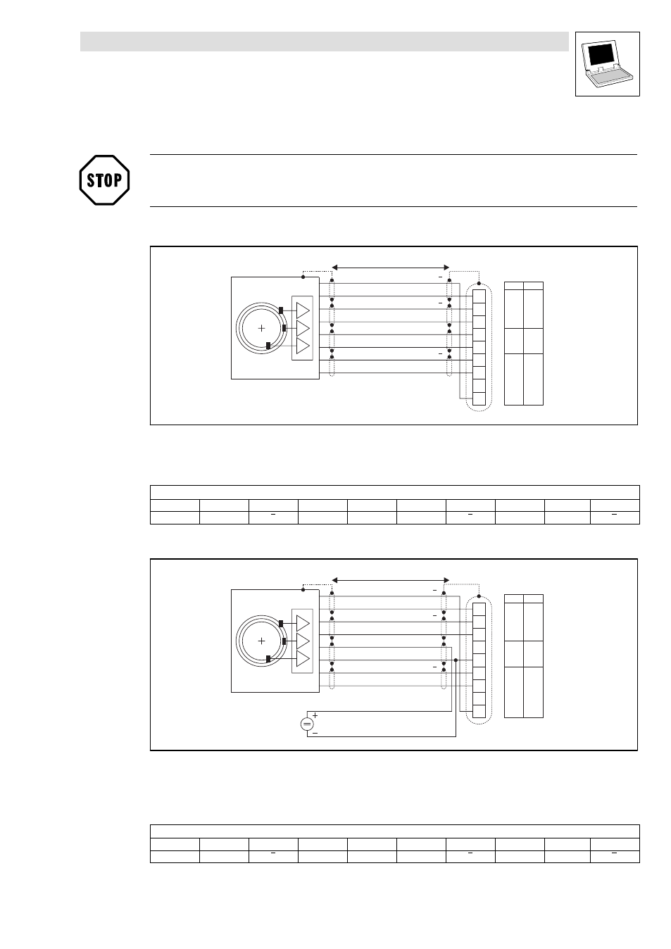
Connection of incremental encoders to terminal X3
Stop!
Observe connection voltage of the incremental encoder used!
Incremental encoder with TTL level
1
2
3
4
5
6
7
8
9
l = max. 50 m
0.14
0.14
1.0
26
26
17
mm
2
AWG
B
B
A
A
GND
V
Z
Z
X3
cc5_E
Fig. 7−6
Connection of incremental encoder with TTL level to terminal X3
Incremental encoder
Cable cross−sections to be used
Assignment of the Sub−D connector (X3)
PIN
1
2
3
4
5
6
7
8
9
Signal
B
A
A
V
cc5_E
GND
Z
Z
−
B
Incremental encoder with HTL level
1
2
3
4
5
6
7
8
9
l = max. 50 m
0.14
0.14
1.0
26
26
17
mm
2
AWG
B
B
A
A
GND
V
Z
Z
X3
cc5_E
Fig. 7−7
Connection of incremental encoder with HTL level to terminal X3
Incremental encoder
Cable cross−sections to be used
Supply voltage for the incremental encoder
Assignment of the Sub−D connector (X3)
PIN
1
2
3
4
5
6
7
8
9
Signal
B
A
A
+5 V
GND
Z
Z
−
B
- ESMD smd tmd remote keypad (4 pages)
- EPM Programmer EEPM1RA (114 pages)
- ESMDC (36 pages)
- SMD Frequency Inverter 0.37kW-22kW (116 pages)
- SMD Frequency Inverter: Basic I/O with CANopen 0.25kW-4.0kW (36 pages)
- SMD 0-25kW-4-0kW (112 pages)
- smd Series Drives (32 pages)
- ESV SMV remote keypad H0 (2 pages)
- ESV SMV remote keypad H1 (2 pages)
- SV SMV additional I-O module (14 pages)
- EEPM1RA EPM (26 pages)
- SMVector RS-485 LECOM (29 pages)
- E84AYM10S (4 pages)
- E84AYCET EtherCAT MCI module (109 pages)
- EZAMBKBM (6 pages)
- E84AYCEC (89 pages)
- ERBPxxxRxxxx Brake resistor 200W-300W (134 pages)
- E84AYCPM (115 pages)
- E84AYCEO (165 pages)
- E84AYCER (94 pages)
- E84AVSCx 8400 StateLine C (76 pages)
- EZVxxxx-000 Power supply unit AC 230V 5A-20A (62 pages)
- E84AYCIB (75 pages)
- E82ZWBRB (48 pages)
- EZVxx00−001 Power supply unit AC 400V 5A-20A (64 pages)
- E82ZWBRE (64 pages)
- EZAEBK1001 (94 pages)
- E94AYAE SM301 (134 pages)
- E94AYAE SM301 (74 pages)
- E94AYAE SM301 (140 pages)
- E94AZPS (114 pages)
- E94AYCIB (124 pages)
- E94AYCIB (78 pages)
- E94AZEX100 (84 pages)
- EZS3-xxxA200 Sinusoidal filter 115-150A (44 pages)
- E94AZHA0051 (104 pages)
- E94AZCDM030 (72 pages)
- EZS3-xxxA200 Sinusoidal filter 180-480A (74 pages)
- E94AYCCA (188 pages)
- E94AYCCA (114 pages)
- E94AZHB0101 (104 pages)
- E94AYCPM (125 pages)
- E94AYCPM (114 pages)
- E94AYCET (103 pages)
- E94AYCET (140 pages)