Aif1_io_automationinterface (node number 41), Inputs_aif1, Drive plc – Lenze Global Drive PLC Developer Studio User Manual
Page 17: System blocks, 1 inputs_aif1, 2 aif1_io_automationinterface (node number 41), Driveplc de 6.0
Drive PLC
System blocks
2.2
AIF1_IO_AutomationInterface (node number 41)
2−3
L
DrivePLC DE 6.0
2.2
AIF1_IO_AutomationInterface (node number 41)
2.2.1
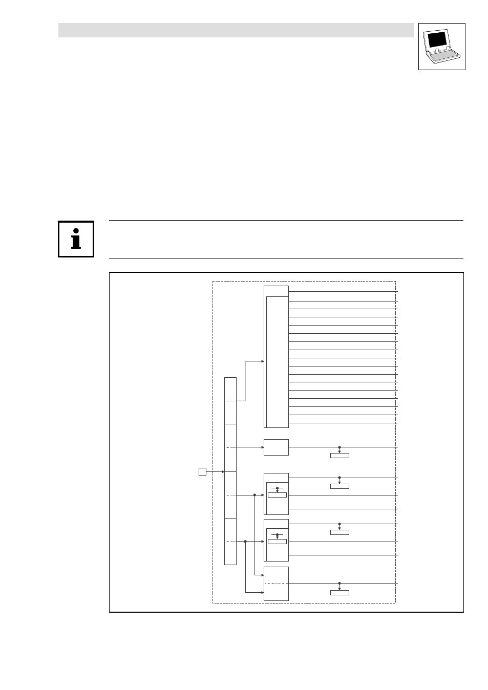
Inputs_AIF1
This SB is used as interface for input signals (e.g. setpoints/actual values) from attached fieldbus
modules (e.g. INTERBUS, PROFIBUS−DP).
·
The process image is
– created every 10 ms.
– created in an interval task within the time set for this task.
– read at the beginning of the task and written at its end.
Tip!
Please observe the Operating Instructions for the attached fieldbus module.
Inputs_AIF1
AIF1_nInW1_a
C0856/1
16 Bit
C0855/2
16 binary
signals
C0857
16 Bit
LowWord
16 Bit
HighWord
AIF1_dnInD1_p
16 Bit
AIF1_wDctrlCtrl
AIF1_bCtrlB0_b
AIF1_bCtrlB1_b
AIF1_bCtrlB2_b
AIF1_bCtrlQuickstop_b
AIF1_bCtrlB4_b
AIF1_bCtrlB5_b
AIF1_bCtrlB6_b
AIF1_bCtrlB7_b
AIF1_bCtrlDisable_b
AIF1_bCtrlCInhibit_b
AIF1_bCtrlTripSet_b
AIF1_bCtrlTripReset_b
AIF1_bCtrlB12_b
AIF1_bCtrlB13_b
AIF1_bCtrlB14_b
AIF1_bCtrlB15_b
16 Bit
16 binary
signals
16 Bit
C0855/1
16 binary
signals
AIF1_nInW2_a
C0856/2
C0856/3
AIF1_bInB0_b
AIF1_bInB15_b
…
…
AIF1_nInW3_a
AIF1_bIn16_b
AIF1_bIn31_b
Automation
Interface
Byte
1
Byte
2
Byte
3
Byte
4
Byte
5
Byte
6
Byte
7
Byte
8
Controlword
Fig. 2−2
Inputs_AIF1