Drive plc, System blocks − extension board 3, 1 encoder input x3 – Lenze Global Drive PLC Developer Studio User Manual
Page 73
Drive PLC
System blocks − Extension Board 3
7.3
DFIN_IO_DigitalFrequency (node number 21)
7−5
L
DrivePLC DE 6.0
7.3.1.1
Encoder input X3
·
Encoder input X3 of the extension board 3 is designed for signals with TTL level.
·
The input of a zero track is optional.
·
The drive can be adapted to the connected encoder or preconnected controller with master
frequency cascade or master frequency bus under C0425.
Code
LCD
Possible settings
IMPORTANT
Lenze
Selection
C0425 DFIN const
3
Extension board 3: DFIN_IO
Increments of the encoder input
0
256 inc/rev
1
512 inc/rev
2
1024 inc/rev
3
2048 inc/rev
4
4096 inc/rev
5
8192 inc/rev
6
16384 inc/rev
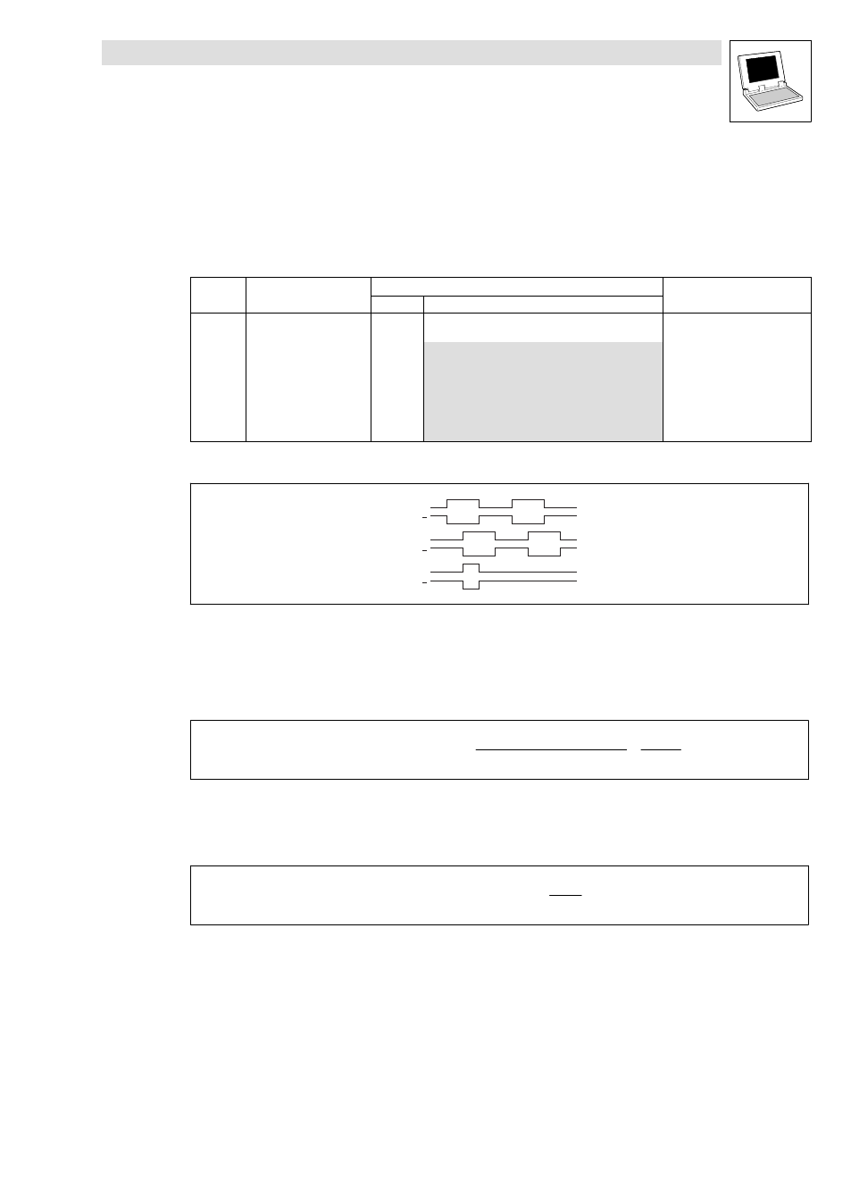
Evaluation of master frequency signals
B
B
A
A
Z
Z
Fig. 7−4
Signal sequence with phase−shift (CW rotation)
·
CW rotation: Track A leads track B by 90 ° (positive value at DFIN_nIn_v).
·
CCW rotation: Track A lags track B by 90 ° (negative value at DFIN_nIn_v).
Transmission function
DFIN_nIn_v
+ f [Hz] @
60
Increments from C0425
@ 2
14
15000
Example:
·
Input frequency = 200 kHz
·
C0425 = 3, this corresponds to 2048 increments/rev.
DFIN_nIn_v [rpm]
+ 200000 Hz @ 60
2048
+ 5859 rpm