3 masking menu – Videotec ULISSE COMPACT THERMAL User Manual
Page 30
EN - English - I
nstruc
tions manual
28
9.6.3.3 Masking menu
Dynamic masking allows the creation of up to a
maximum of 24 masks so as to obtain the masking of
certain areas defined by the user.
Masks are defined in space and take account of the
horizontal, vertical and zoom depth position when
making the settings.
ULISSE COMPACT THERMAL automatically maintains
the position and dimension of the masking, based on
the displayed area.
It is possible to simultaneously display up to 8 masks.
If the device is used at maximum speed, video signal
updating times become critical and it is necessary to
create masks larger than the object so that it remains
masked for longer during the passage and therefore
cannot be seen.
j
To ensure full functionality, the tilt position
of the masks must always be between -70
and +70 degrees; in addition , the size of
the mask must be double the size of the
object to be masked (both height-wise and
width-wise).
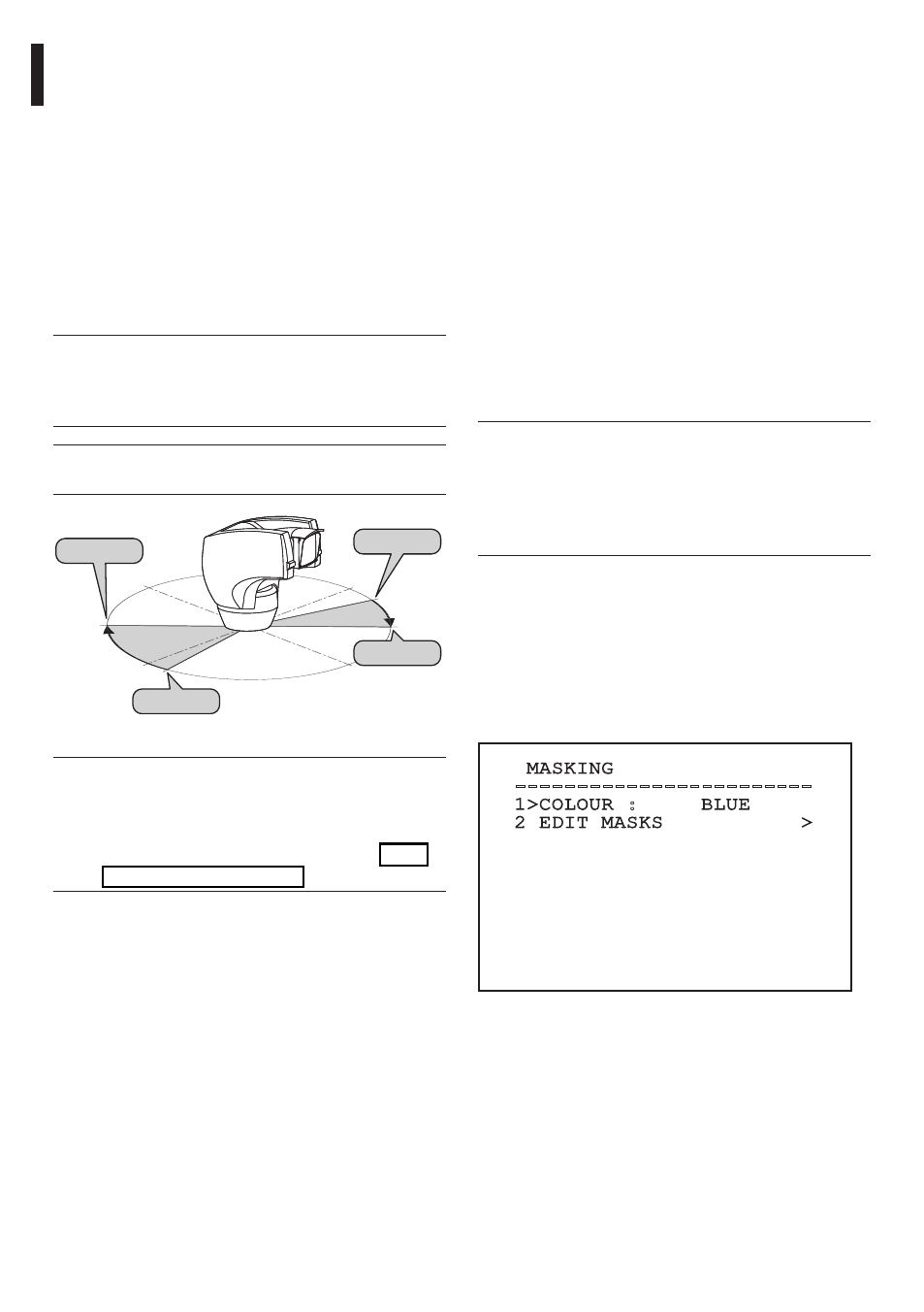
From the Masking menu it is possible to set the
following parameters:
01. Mask Colour: Allows you to choose the colour
of the masks.
02. Edit Masks: Allows access to the Edit Masks
submenu and set the dynamic masking
parameters.
MASKING
------------------------
1>COLOUR : BLUE
2 EDIT MASKS >
Fig. 52
Example: To enable titling of zone 1 when the device
is between +15° and +45°, it is necessary to:
• Enable area titling by setting Y as the value of
Enabling under the Area Titling menu.
• Set 1 as the value of parameter Nr under the Edit
Area menu.
• Set +15.00 as the value of parameter Start under
the Edit Zone menu.
• Set +45.00 as the value of parameter Stop under
the Edit Zone menu.
• If necessary, edit the displayed text by selecting
Text under the Edit Zone menu.
j
Setting the Start and Stop values of the Edit
Zone menu to zero will disable text display.
If there are overlapping areas, the area with
the highest number will prevail.
j
To define zones proceed in a clockwise
direction, as shown in the figure.
0°
Start1=15°
Stop1=45°
Start2=170°
Stop2=135°
-90°
90°
-180°
Fig. 51
j
The default name and position of the
zones of the pan & tilt refer to the four
cardinal points. The NORTH position can
be modified by means of the Offset Pan
parameter in the movement menu ("9.6.4
Movement menu", page 33).