4 one-way rs485 line, 15 serial line terminations (dip1) and connections, 16 setting the protocol (dip3) – Videotec ULISSE COMPACT THERMAL User Manual
Page 24: 17 setting the address (dip2)
EN - English - I
nstruc
tions manual
22
7.1.16 Setting the protocol (DIP3)
Video positioning systems with the ULISSE COMPACT
THERMAL line can be controlled by a range of
protocols.
SETTING THE PROTOCOL (DIP3)
SW 1 SW 2 SW 3 SW 4 Protocol
ON
OFF
ON
OFF
PANASONIC
OFF
OFF
ON
OFF
ERNITEC
OFF
ON
OFF
OFF
SENSORMATIC
ON
OFF
OFF
OFF
PELCO D
OFF
OFF
OFF
OFF
MACRO (VIDEOTEC)
Tab. 12
7.1.17 Setting the address (DIP2)
ULISSE COMPACT THERMAL address can be set from
1 to 1023. The address is selected based on the
binary coding, by means of DIP2 10 dip-switches ("16
Appendix A - Dip-switch address table", page 55).
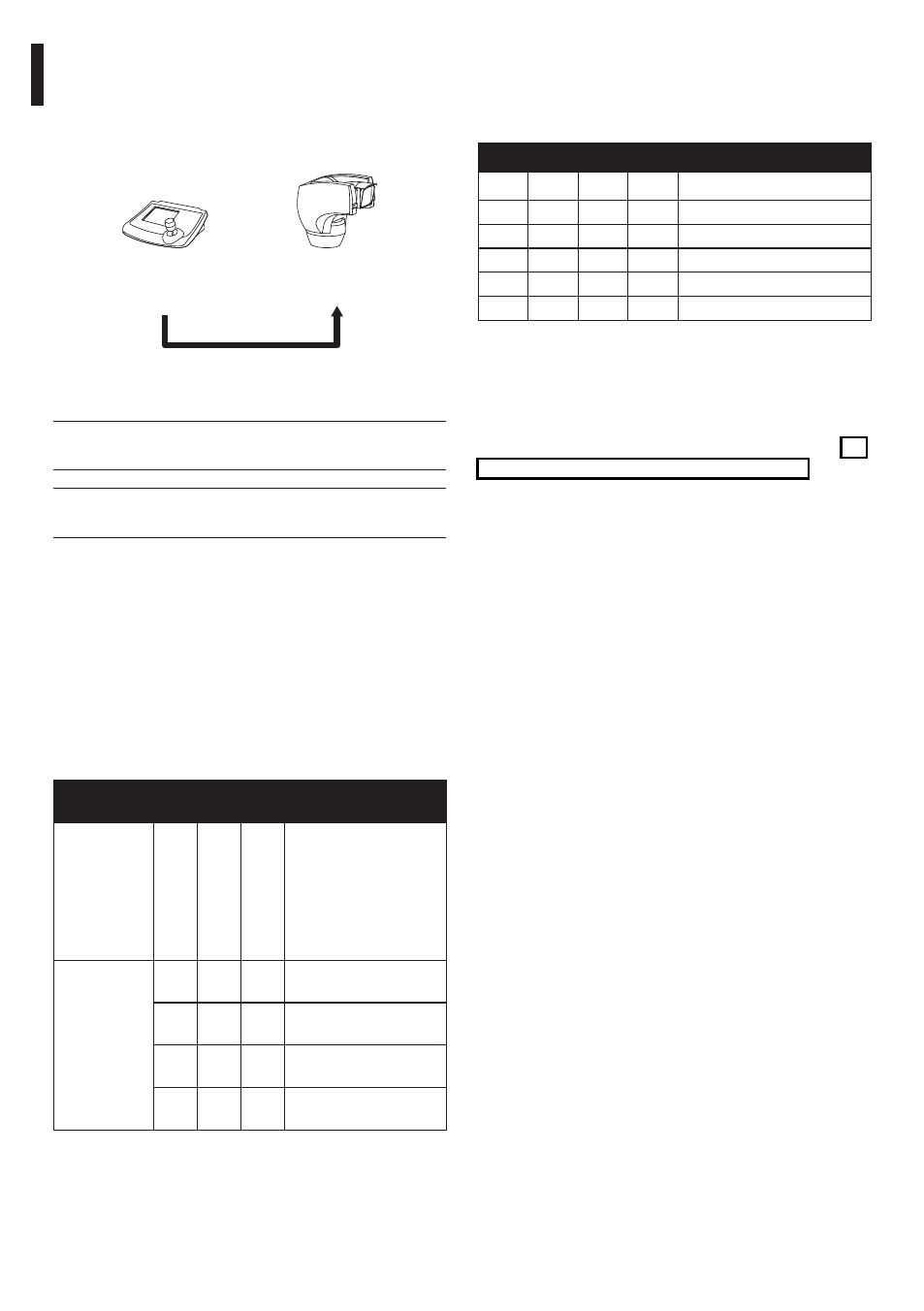
7.1.14.4 One-way RS485 line
The first line (RS485-1) will operate according to the
settings in the Address, Baudrate and Protocol
dip-switch.
The RS485-2 serial line is not used.
RS485-1
Max 1200m
Control
keyboard
Fig. 31
j
It only works with mono-directional
protocols.
j
This configuration does not allow the
remote updating of the firmware.
7.1.15 Serial line terminations (DIP1)
and connections
The diagram shows two dip-switches that are used to
configure termination of the serial line.
Every peripheral that is situated at the end of a line
must be terminated using the appropriate dip-switch
in order to prevent signal reflection and distortion.
Dip-switches 7 and 8 terminate serial lines RS485-1
and RS485-2 respectively.
SERIAL LINE TERMINATIONS (DIP1) AND
CONNECTIONS
Description
SW 1-2-3-4-5-6
SW 7
SW 8
C
onfigur
ation
Serial line
termination
ON
RS485-2 termination
enabled
OFF RS485-2 termination
disabled
ON
RS485-1 termination
enabled
OFF
RS485-1 termination
disabled
Tab. 11