11 dip-switch configuration, 12 setting the configuration check mode (dip1), 13 setting the baud rate (dip1) – Videotec ULISSE COMPACT THERMAL User Manual
Page 22
EN - English - I
nstruc
tions manual
20
7.1.12 Setting the configuration check
mode (DIP1)
• SW1=ON: Display Configuration. To be used only
to verify the configuration at the end of the setting.
During normal operation make sure the lever is on
OFF (DIP1=OFF).
7.1.13 Setting the baud rate (DIP1)
Dip-switches 4, 3 and 2 are used to set the
communication rate of the device according to the
table below.
SETTING THE BAUD RATE (DIP1)
Description
SW 1
SW 2
SW 3
SW 4
SW 5-6-7-8
C
onfigur
ation
Baud-rate
selection
-
ON ON ON -
38400 baud
-
OFF ON ON -
19200 baud
-
ON OFF ON -
9600 baud
-
OFF OFF ON -
4800 baud
-
ON ON OFF -
2400 baud
-
OFF ON OFF -
1200 baud
-
ON OFF OFF -
600 baud
-
OFF OFF OFF -
300 baud
Configurations
display
ON
-
-
-
Display
enabled
OFF
-
-
-
Display
disabled
Tab. 09
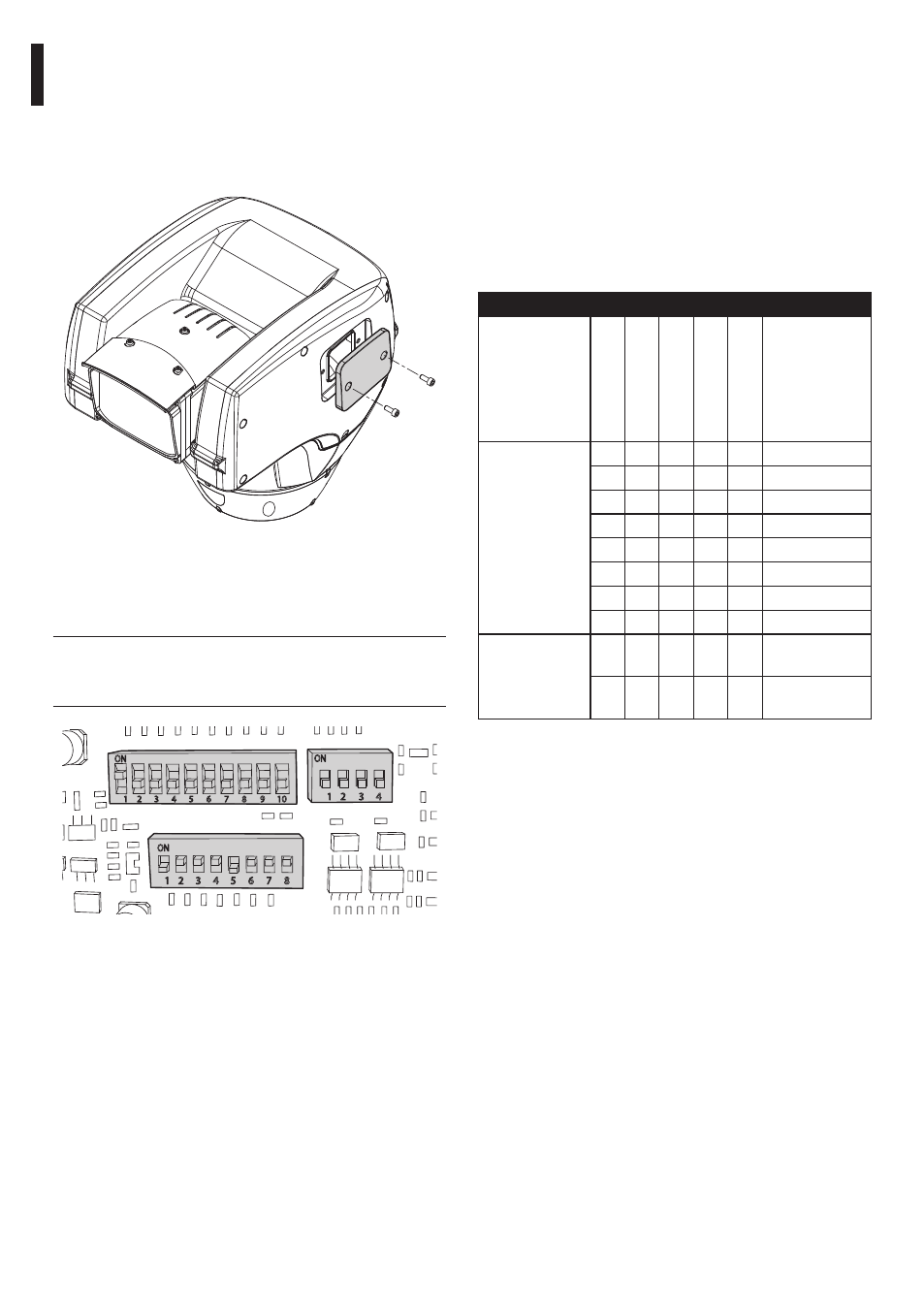
7.1.11 Dip-switch configuration
Before powering the device it must be configured
correctly by setting the dip-switches inside the
configuration window.
Open the window by undoing the screws as shown in
the illustration:
Fig. 26
The following diagram represents the position of
the dip-switches when the configuration window is
opened.
h
When the dip-switch rocker (SW) is up it
represents the value 1 (ON) while if it is
down it represents the value 0 (OFF).
DIP2
DIP3
DIP1
Fig. 27