4 video cables connection, 1 connecting the main video, 2 connecting the secondary video – Videotec ULISSE COMPACT THERMAL User Manual
Page 17: Awg16) and 0,5mm, Awg30), J7 j5
EN - English - I
nstruc
tions manual
15
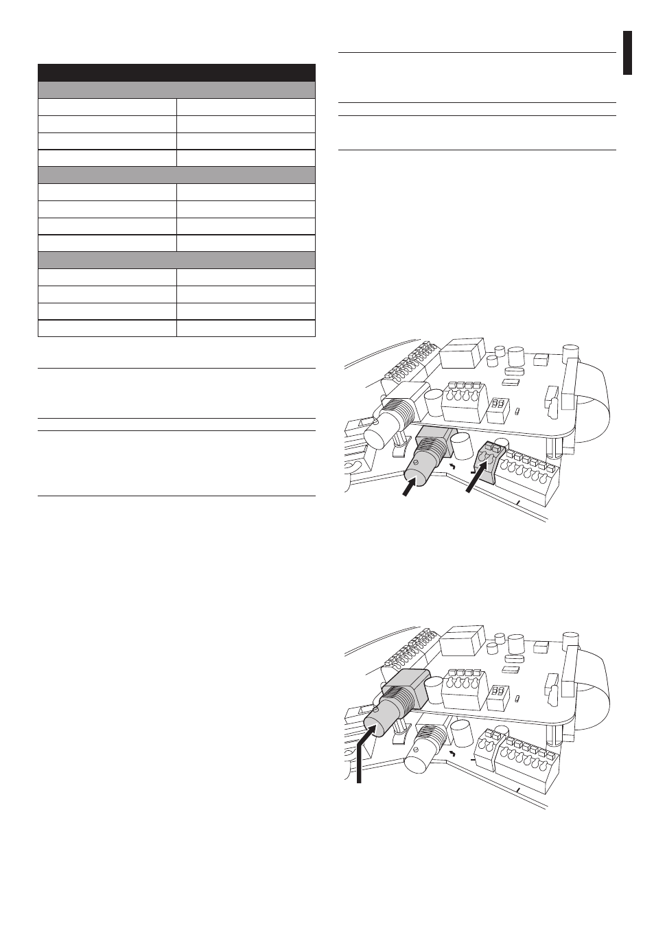
7.1.4 Video cables connection
h
The installation is type CDS (Cable
Distribution System), do not connect it to
SELV circuits.
h
In order to reduce the risk of fire, only use
cable sizes greater than or equal to 26AWG.
7.1.4.1 Connecting the main video
The video signal is present on connectors J5 and J7 of
the board. Only use one connector.
Connector J5: Connect the screen and the central
cable to terminals GND and CVBS respectively.
J7 connector: Connect the coaxial cable to the BNC
connector (not supplied) and then connect it to
connector J7.
The terminals accept cables with sections between
1.5mm
2
(AWG16) and 0,5mm
2
(AWG30).
SGND
VIDEO OUT
CVBS
GND
A
B
A
B
SGND
RS485-1
RS485-2
SGND
A
B
SW1
1
2
TH
IC11
J7
J5
Fig. 13
7.1.4.2 Connecting the secondary video
CN3 connector: Connect the coaxial cable to the
BNC connector (not supplied) and then connect it to
connector CN3.
SGND
VIDEO OUT
CVBS
GND
A
B
A
B
SGND
RS485-1
RS485-2
SGND
A
B
SW1
1
2
TH
IC11
CN3
Fig. 14
Connect the power supply cables to the clamp as
described in the table below:
POWER SUPPLY CONNECTION
Power supply 24Vac
Colour
Clamps
Defined by the installer
(N) Neutral
Defined by the installer
(L) Phase
Yellow/Green
Earth
Power supply 230Vac
Colour
Clamps
Blue
(N) Neutral
Brown
(L) Phase
Yellow/Green
Earth
Power supply 120Vac
Colour
Clamps
Blue
(N) Neutral
Brown
(L) Phase
Yellow/Green
Earth
Tab. 01
h
Only for products marked UL intended for
the North American market, use a class 2 UL
listed transformer.
h
Use the appropriate junction-box UPTJBUL
to connect the power supply line. For
further information, refer to the product
use and installation manual.