2 relay connection – Videotec ULISSE COMPACT THERMAL User Manual
Page 20
EN - English - I
nstruc
tions manual
18
7.1.9.2 Relay Connection
Relays are located inside R1A and R1B (Relay 1) and
inside R2A and R2B (Relay 2) connectors. Relays do
not have polarity and therefore both terminals A or
B of the same relay can be used, for alternating or
continuous current voltages.
TERMINAL
DESCRIPTION
R1A
Relay 1 terminal A
R1B
Relay 1 terminal B
R2A
Relay 2 terminal A
R2B
Relay 2 terminal B
Tab. 06
h
Relays can be used for low working
voltages only (up to 30 Vac or 60 Vdc) and
with a maximum current of 2A. Use cables
with a section suitable for the load to be
controlled. The terminal can house cables
with a section comprised between 0.5 and
1.5mm
2
(AWG 30-16).
For further details on configuring and using the
relays, refer to "9.6.6.1 Alarms menu", page 37, page 38.
TERMINAL
DESCRIPTION
W
Washer float alarm *
G
W alarm ground or A1-A5 alarms ground
A1
Alarm 1 (clean contact)
G
A1-A2-A3-A4 A5 alarms ground
A2
Alarm 2 (clean contact)
A3
Alarm 3 (clean contact)
A4
Alarm 4 (clean contact)
A5
Alarm 5 (clean contact) **
Tab. 05 *Alarm input contemplated only for UPTWAS, to check
the level of liquid in the Washer tank.
All alarms have an approximate reach of 200 metres,
which can be obtained using an unshielded cable
with a minimum section of 0.25 sq.mm. (AWG 24).
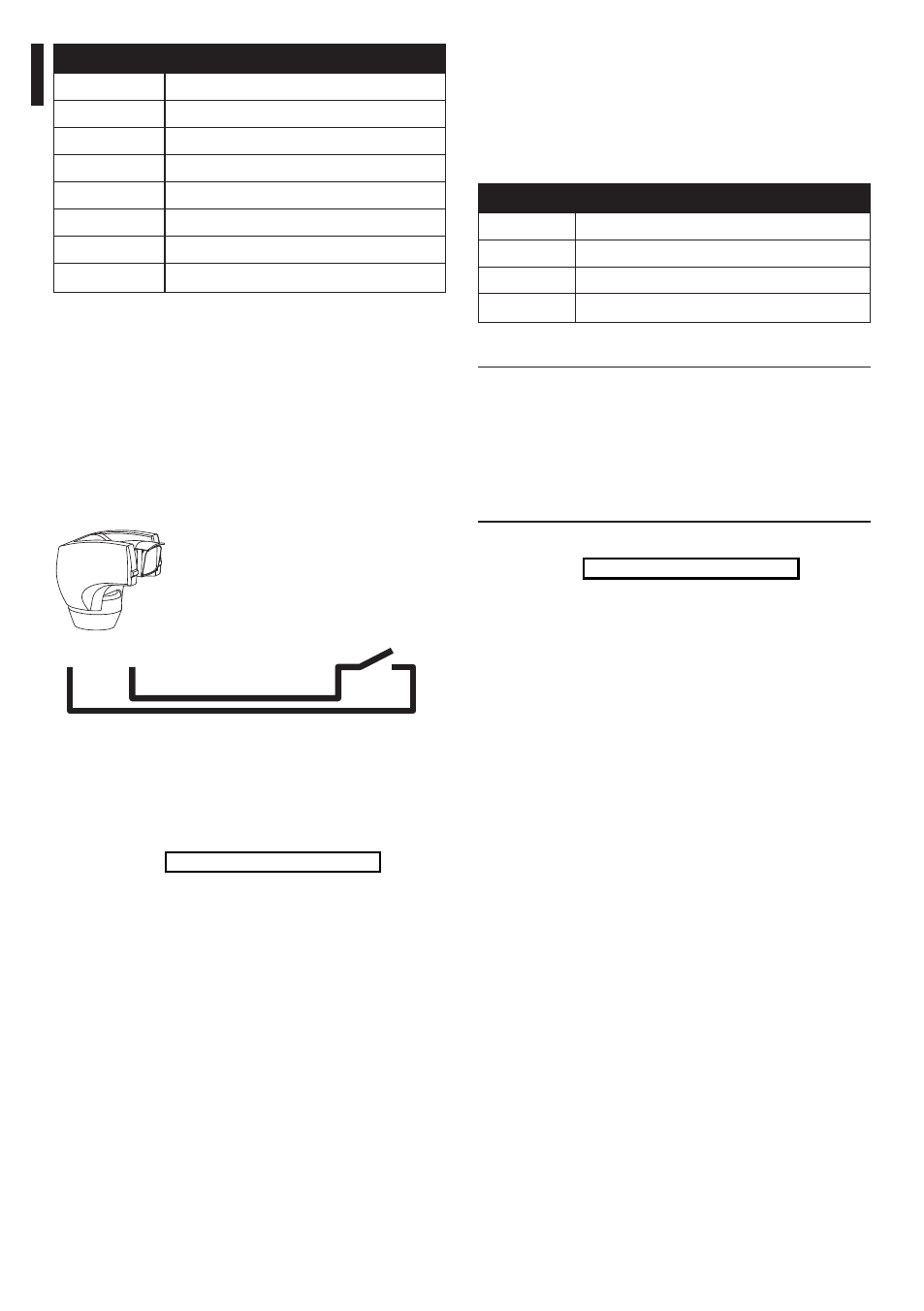
7.1.9.1 Connecting an alarm with clean
contact (dry contact)
For a clean contact alarm (alarms A1, A2, A3, A4 and
A5), carry out the following connection:
Max 200m
A1
G
Clean
contact
Fig. 21
The alarm switch can be NO (normally open) or NC
(normally closed).
For further details on configuring and using the
alarms, refer to "9.6.6.1 Alarms menu", page 37.