V. map card, Slopes card, Fill hinge points card – Spectra Precision Survey Pro v3.80 Recon iPAQ Reference Manual User Manual
Page 235
Roads Menu
R-229
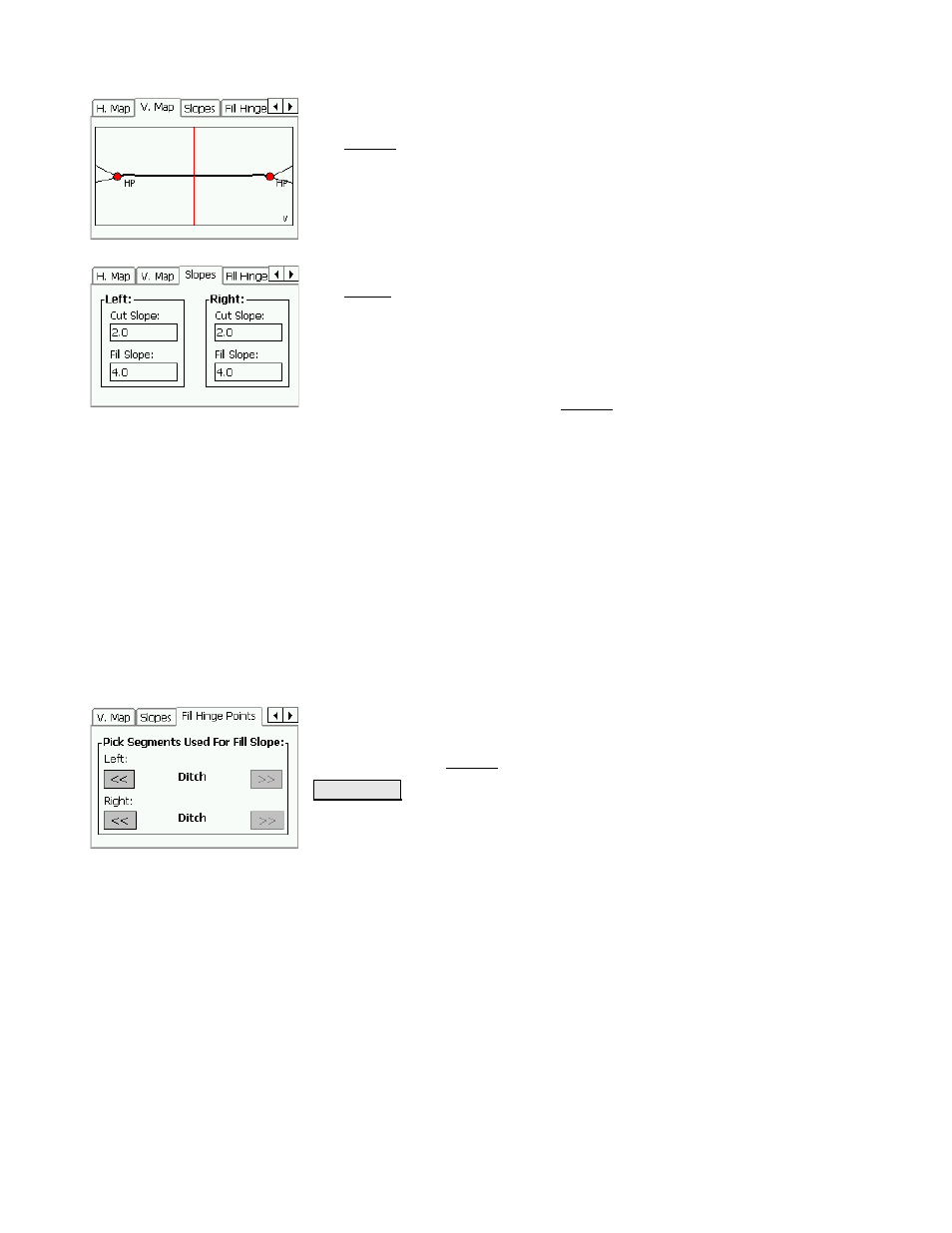
V. Map Card
The V. Map card displays a graphic of the cross-sectional
profile of the road at the current station. The hinge
points and slopes are also displayed.
Slopes Card
The Slopes card is used to specify the desired cut and fill
slopes that will be used when computing the location of
the catch points. These values are always initialized
from the templates every time the station to be staked is
modified. You can then override these default values
here to account for terrain constraints. Changes to slopes
will be adequately reflected in the V. Map card graphic.
Cut Slope
: is the left and right slope, respectively, to use when the
terrain requires a cut (the hinge point is located below the terrain’s
surface).
Fill Slope
: is the left and right slope, respectively, to use when the
terrain requires a fill (the hinge point is located above the terrain’s
surface).
Fill Hinge Points Card
When the terrain requires a fill, you have the option to compute the
hinge point at any existing template segment. The option to use a
segment other than the last segment can simplify the situation where
a ditch meets an area requiring a fill, which would otherwise result in
an area with two similar or identical negative slopes.
Left
/
Right
: is the specified left and right segment,
respectively, to compute the hinge point from in a
situation that requires a fill. Changes to these fields will
be reflected in the V. Map card graphic.
6WDNH &3 ! : opens the next slope staking screen. The
following slope staking screens are identical to non-road
layout slope staking screens and are described starting
on Page R-130.