Yokogawa Data Logging Software GA10 User Manual
Page 58
3-34
IM 04L65B01-01EN
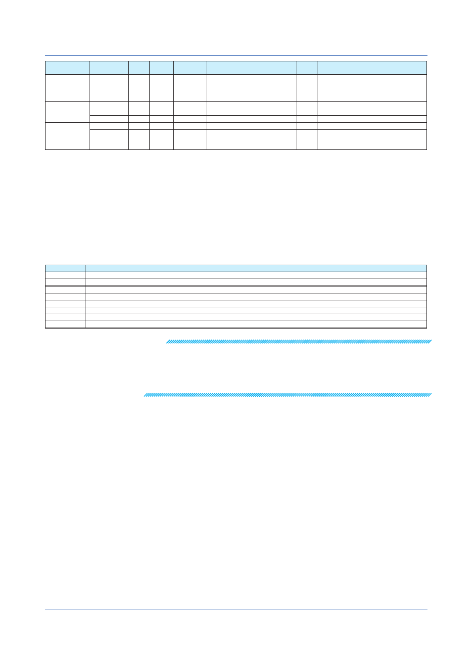
Node Name
Attribute
Type
Type
Mandatory
Range
Default
Value
Description
Alarm\Type
Kind
enum enum
“OFF”,“H”,“L”,“dH”,“dL”,“RH”,“RL”,
“tH”,“tL”,“PVH”,“PVL”,“DVH”,“DVL”
,“DVO”,“DVI”,“SPH”,“SPL”,“OTH”,“
OTL”,“ETC”
“OFF” Default alarm type
Table
Name
string
string
(C)
Alphanumeric characters, 1 to 15
characters
Value conversion table name
ToDataType
enum enum
Int, String
Int
Target conversion data type
Value
From
int
*2
int
*2
(C)
-2147483648 to 2147483647
Conversion source value
To
string
string
(C)
Up to 15 Unicode characters
Conversion target value
To convert to a value, specify the value
using a character string.
(A): Mandatory item. However, for attribute name Register, node name Type is not mandatory.
(B): Mandatory item to use the option
(C): Mandatory item to convert data
1 If only a mask is available, bit mask is applied to the data value read from the register, and the result is handled as TRUE or FALSE.
2 Decimal and Hexadecimal integers are supported. For hexadecimals, the number must be preceded by a “0x.”
3 For a description of Data Type, see the table below.
4 Scaling calculation: Y = ScaleRatio * X + ScaleOffset
X: Modbus register value (after decimal point calculation; after conversion is a value conversion table is available)
Y: Computed result
5 Channel data status is processed in the following order of precedence: ADError, DataError, Burnout, PlusOver, MinusOver.
6 If the burnout type is set to DownScale (type value is 2) and the burnout status is 1, the data status will be −BURNOUT. If the burnout type is set to UpScale (type value is not 2)
and the burnout status is 1, the data status will be +BURNOUT.
7 Node channels include optional attributes. When registering a device in the Register Device dialog box, if you do not select this option, this channel will not be available in
the registered device.
Description of Data Type
Value
How to Use
INT16
Use when a signed 16-bit integer is assigned to the device register.
UINT16
Use when an unsigned 16-bit integer is assigned to the device register.
INT32_B
Use when a signed 32-bit integer is assigned to the device register and the smallest register number is assigned to the highest bit.
INT32_L
Use when a signed 32-bit integer is assigned to the device register and the smallest register number is assigned to the lowest bit.
UNIT32_B
Use when an unsigned 32-bit integer is assigned to the device register and the smallest register number is assigned to the highest bit.
UINT32_L
Use when an unsigned 32-bit integer is assigned to the device register and the smallest register number is assigned to the lowest bit.
FLOAT_B
Use when a 32-bit floating-point number is assigned to the device register and the smallest register number is assigned to the highest bit.
FLOAT_L
Use when a 32-bit floating-point number is assigned to the device register and the smallest register number is assigned to the lowest bit.
Note
A read error will occur in the following situations.
• A mandatory item is missing.
• There is a syntax error. However, in the following situations, an error will not occur and the value
will be corrected when it is read.
• There is a limit to the string length for a node attribute, and this limit is exceeded.
• There is an allowable range for a node attribute, and the value is outside the range.
A sample Modbus device definition file is provided in the following pages. The sample shows
how the XML file should be structured.
When you create a Modbus device definition file, refer to the description of registers in
the user's manual of the Modbus device that you want to connect.
Chapter 3 Configuring and Starting Data Collection and Recording