Yokogawa Data Logging Software GA10 User Manual
Page 57
3-33
IM 04L65B01-01EN
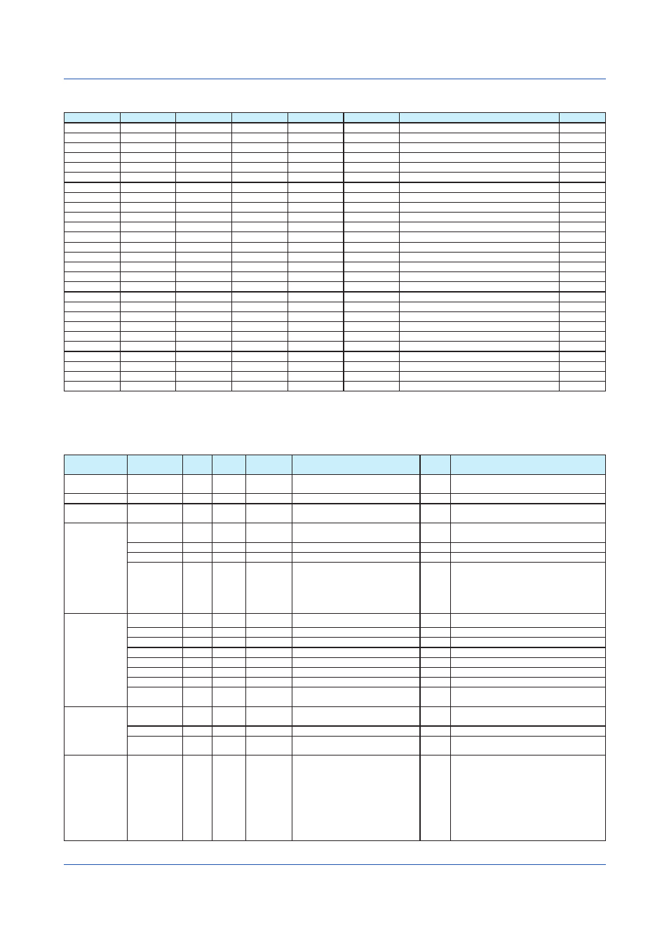
Node Structure of Modbus Device Definition Files
Level 0
Level 1
Level 2
Level 3
Level 4
Level 5
Description
Quantity
ModbusDevice
Definition file root element
1
Options
Option list node
0 or 1
Option
Option information
0 to 5
Registers
Register list node
1
Register
Register information
1 to 300
Channels
Channel list node
1
Channel
Channel information
1 to 300
Init
Channel default setting
0 or 1
DecimalPos
Default decimal place
0 or 1
Min
Default minimum span
0 or 1
Max
Default maximum span
0 or 1
Unit
Default unit
0 or 1
Value
Channel value
1
DataError
Error data status
0 or 1
ADError
A/D converter status
0 or 1
PlusOver
+OVER status
0 or 1
MinusOver
-OVER status
0 or 1
Burnout
Burnout information
0 or 1
Type
Burnout type
0 or 1
Value
Burnout status
0 or 1
Alarms
Alarm list node
0 or 1
Alarm
Alarm information
0 to 4
Type
Alarm Type
0 or 1
Value
Alarm value
0 or 1
TransTables
Value conversion table node
0 or 1
Table
Value conversion table
0 to 100
Value
Conversion value
0 to 100
Node Attributes of Modbus Device Definition Files
If an attribute is not specified, the default value will be applied. However, if the Option, Mask, or Trans attribute is not
specified, GA10 assumes that the corresponding function is not used and does not apply the default value.
Node Name
Attribute
Type
Type
Mandatory
Range
Default
Value
Description
ModbusDevice
Type
string
string
(A)
Alphanumeric characters, 1 to 15
characters
Modbus device type
double
0.5 to 60.0
1
Option
Name
string
string
(B)
Alphanumeric characters, 1 to 15
characters
Names of options supported by the
Modbus device
Register
Name
string
string
(A)
Alphanumeric characters, 1 to 15
characters
Register names in the Modbus device
FunctionCode int
int
(A)
3 or 4
Modbus communication function code
Address
int
*2
int
*2
(A)
1-465535
Modbus register
DataType
enum enum
(A)
I
NT16,UNIT16,INT32_B,INT32_L,
UINT32_B,UINT32_L,FLOAT_B,F
LOAT_L
*3
Read data type
Channel
Name
string
string
(A)
1 to 15 Unicode characters
Channel name
DecimalPos
int
int
0 to 5
0
Channel decimal place
Min
double double
-1E16 to 1E16
0
Minimum channel span
Max
double double
-1E16 to 1E16
100
Maximum channel span
ScaleRatio
double double
-1E16 to 1E16
1
Channel scaling coefficient
ScaleOffset
*4
double double
-1E16 to 1E16
0
Channel scaling offset
Unit
string
string
Up to 6 Unicode characters
“”
Channel unit
Option
string
string
Alphanumeric characters, up to 15
characters
Option name
DecimalPos
Min
Max
Register
string
string
(A)
Alphanumeric characters, 1 to 15
characters
Register name
Mask
*1
int
*2
int
*2
Hexadecimal number, 0 to 65535
Data bit mask
Trans
string
string
Alphanumeric characters, up to 15
characters
Value conversion table name
Unit
DataError
*5
ADError
*5
PlusOver
*5
MinusOver
*5
Burnout\Type
*5*6
Burnout\Value
Alarm\Type
Alarm\Value
Chapter 3 Configuring and Starting Data Collection and Recording