Signal description (arbitrary/dds mode), Arbstudio – Teledyne LeCroy ArbStudio User Manual
Page 146
ArbStudio
138
922244-00 Rev A
Signal Description (Arbitrary/DDS Mode)
The signals available on ArbStudio 1102D/1104D probes connected to
digital output connectors are as follows:
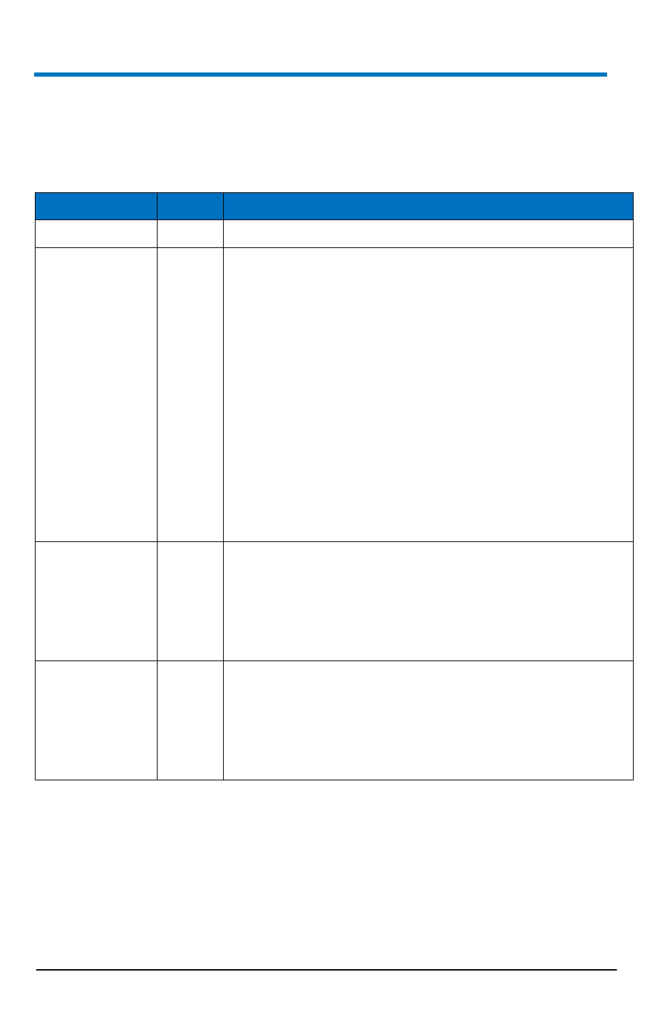
Signal Name
Type
Description
DGND
Digital ground
DP[0..17] DP
[9...16]
Output
Digital pattern output. When channel 1 and 2 are
configured as Arbitrary Waveform Generators, the 16-bit
digital representation of the analog waveform of channel 1
is available on DP[0..7] and DP[9..16] of Pod A if Channel
1 Digital Pattern on Pod A is enabled. See Setup Device
(on page 49).
When channel 3 and 4 are configured as Arbitrary
Waveform Generators (ArbStudio 1102/1104 only), the
16-bit digital representation of the analog waveform of
channel 3 is available on DP [0..7] and DP[9..16] of Pod B
if Channel 3 Digital Pattern on Pod B is enabled.
The bit assignment to Pod Channel is:
DP[0..7] ≤ SampleBit[0..7]
DP[9..16] ≤ SampleBit[8..15]
DP[8] and DP[16] are not significant.
DC_TO
Output
Digital Connector Trigger out.
When DC Trigger Out Destination is enabled (see Trigger
out menu): trigger out signal combination of CH1 and
CH2 is sent to DC_TO on Pod A, trigger out signal
combination of CH3 and CH4 is sent to DC_TO on Pod B
(1104 ArbStudio only).
DC_TI
Input
Digital Connector Trigger IN.
When DC Trigger IN Source is enabled (see Settings
→Trigger IN menu), trigger in signal of CH1/CH2 is
acquired from DC_TI pin on Pod A, trigger in signal of
CH3/CH4 is acquired from DC_TI pin on Pod B (1104
ArbStudio only).