4 analysis (reports), 5 recording, 4 analysis (reports) 4.3.5 recording – Teledyne LeCroy USBTracer_Trainer - Users Manual User Manual
Page 94
Chapter 4: Software Overview
USB Protocol Suite User Manual
80
LeCroy Corporation
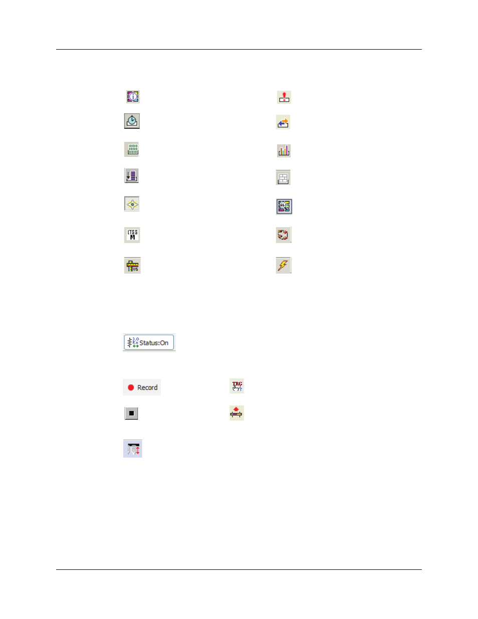
4.3.4 Analysis (Reports)
4.3.5 Recording
File Information Report
See “File Information” on page 177.
Error Report
See “Error Summary” on page 179.
Timing and Bus Usage Calculations
See “Timing Calculations” on page
180.
Traffic Summary
See “Traffic Summary” on page 184.
Data View
See “Detail View” on page 205.
Bus Utilization
See “Bus Utilization” on page 186.
Link Tracker
See “Link Tracker (3.0)” on page
193.
Spec View
See “Spec View (3.0)” on page 206.
Open the Navigator bar
See “Using the Trace Navigator” on
page 198.
Detail View
See “Detail View” on page 205.
Show USB3 Link State Timing View.
Show USB3 LTSSM View
See “USB3 LTSSM View” on
page 209.
Run Verification Scripts.
See “Running Verification Scripts” on
page 212.
Show Power Tracker.
(Power captures are supported only
on Voyager M3i.)
See “Power Tracker” on page 210.
Superspeed (USB 3.0) receiver terminations of Analyzer:
M3i: If both Analyzer ports are set to Auto in Recording Options, this button
is dimmed. If either port is set to Manual, this button can apply or
remove USB 3.0 termination.
M3: This button is always enabled, and Auto mode is not supported.
Start Recording
Manual Trigger
Stop Recording
Repeat Upload
Momentary VBus Disconnect (Voyager M3i Only)
Causes the VBus power between the Host and the Device connected through
the Analyzer A and B USB ports to be broken for 1 second, simulating a
unplug-plugin cycle. This is the recommended method of creating plug-in
scenarios.
Note: When Disconnect is done during recording, it may cause capturing of IPS
(undecodable symbols) and false triggering of CRC triggers, because packets
will be abruptly stopped in the middle of a symbol stream.