1 pin-outs for the data in/out connector, 2 prototype rework area, 3 pc connection – Teledyne LeCroy USBTracer_Trainer - Users Manual User Manual
Page 60
Chapter 2: General Description
USB Protocol Suite User Manual
46
LeCroy Corporation
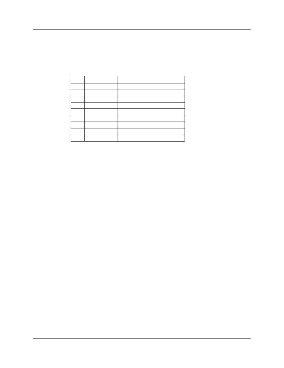
2.17.1 Pin-Outs for the Data In/Out Connector
Table 2 lists the pin-out and signal descriptions for the Data In/Out connector on a cable
that connects to the Breakout Board.
Table 2
Data In/Out Connector – Pin-Out
Note:
(*)
Pins 2 and 3 have the same function: they allow external signals to be
used to cause triggering or recording. Pins 4 and 5 are used to transmit
output signals.
2.17.2 Prototype Rework Area
The Breakout Board contains a prototype rework area for making custom circuits for rapid
development. The area consists of plated-through holes, 20 columns wide by 27 rows
long. The top row of holes connects to GND, and the bottom row connects to +5 V. The
remaining holes are not connected. Use the rework area to insert custom components
and wire-wrap their respective signal, power, and ground pins.
2.17.3 PC Connection
Use the LONGEST (6-foot/2-meter) of the five USB cables provided to connect the host
computer to the Analyzer box.
Pin
Signal Name
Signal Description
1
+5V
+5 Volts, 250mA DC source
2
TRG IN
(*) Trigger Input
3
GP IN
(*) General Purpose Input
4
TRG OUT
(*) Trigger Output
5
GP OUT
(*) General Purpose Output
6
GND
Ground
7
GND
Ground
8
GND
Ground
9
GND
Ground