IAI America CON-PGA User Manual
Page 46
5. Operation of CON Related Controllers
38
Zone output signal
Zone output signal
Zone output signal
H
om
e
Backward en
d
Forward en
d
Midway point
(7) Incremental
Specify absolute coordinates or incremental coordinates.
The factory setting is 0.
0: Absolute coordinate specification
1: Incremental coordinate specification
Warning: Be sure to specify absolute coordinates on PCON-C/CG/CF, PCON-CA, ACON-C/CG,
SCON-C, SCON-CA, ROBONET, ERC3 PIO Converter and MSCON (Remote I/O
mode) controllers of solenoid valve mode 2, or PCON-CY and ACON-CY controllers of
solenoid valve mode 1.
If incremental coordinates are specified on these controllers, a position data error
occurs.
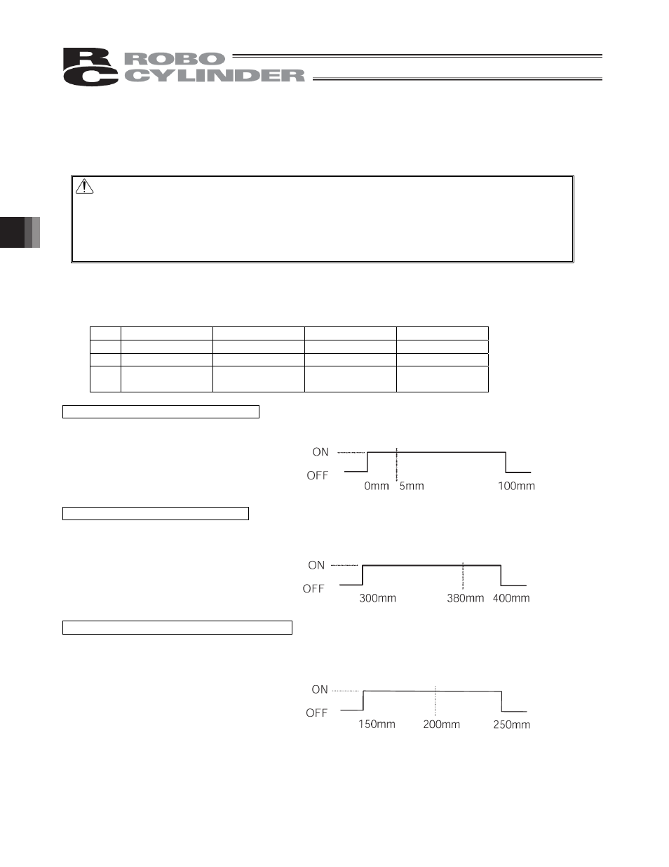
(8) Zone +/-
Define, for the standard type, the zone in which the zone output signal turns ON.
For added flexibility, these parameters can be set differently for each target position.
[Setting example]
No.
Position [mm]
Zone + [mm]
Zone - [mm]
Remarks
0
5.00
100.00
0.00
Backward end
1
380.00
400.00
300.00
Forward end
2
200.00
250.00
150.00
Intermediate
position
Movement command to backward end
Movement command to forward end
Movement command to intermediate position
(9) Threshold
With PCON-C/CG/CF, PCON-CA controllers, a load output signal (PIO) is output if the command torque
exceeds the value (%) set in "Threshold" inside the verification range.
The verification range is set by "Zone+/Zone-."
It is used to determine if press-fitting action was performed successfully.
* For details, refer to the operation manual for your PCON-C/CG/CF, PCON-CA controller.