IAI America ERC2 User Manual
Page 50
0
4. W
iring
31
z
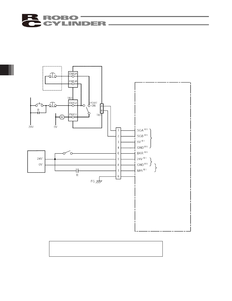
Connection diagram
An example of serial communication connection, including an emergency stop circuit, is shown below.
Emergency stop is actuated by means of cutting off the motor drive power.
*1 The wire colors for standard cables and robot cables are
different. The colors in parentheses are for robot cables.
ERC2-SE actuator
Serial communication
Orange (Blue)
Blue (Yellow)
Brown (Red)
Green (Black)
Gray (Gray)
Red (Purple)
Black (Orange)
Yellow (Green)
Teaching pendant
EMG
pushbutton
SIO converter
TP connector
EMG reset
switch
EMG
pushbutton
Terminal
block
Power supply
The brake is released when
the contacts are closed.
I/F connector
Brake release (24 V, 150 mA)
Control power, 24 V
Motor drive power, 24 V
Shield
See also other documents in the category IAI America Hardware:
- ERC2 (188 pages)
- ERC3 (438 pages)
- ERC (153 pages)
- RCA-E (53 pages)
- RCA-P (42 pages)
- RCB-101-MW (38 pages)
- RCP2-C (178 pages)
- RCS-E (102 pages)
- RCA-A4R (72 pages)
- RCA-RA3C (114 pages)
- RCA-SRA4R (56 pages)
- RCA2-RA2AC (100 pages)
- RCA2-SA2AC (92 pages)
- RCA2-TA4C (134 pages)
- RCD-RA1D (40 pages)
- RCP2-BA6 (72 pages)
- RCP2-GRSS (130 pages)
- RCP2-HS8C (126 pages)
- RCP2-RA2C (120 pages)
- RCP2-RTBS (80 pages)
- RCP2W-SA16C (46 pages)
- RCP3-RA2AC (60 pages)
- RCP4-RA5C (82 pages)
- RCP4-SA5C (94 pages)
- RCP4W (96 pages)
- RCS2-F5D (142 pages)
- RCS2-GR8 (46 pages)
- RCS2-RN5N (80 pages)
- RCS2-RT6 (60 pages)
- RCS2-SA4C (258 pages)
- RCS2-TCA5N (62 pages)
- RCL-SA1L (66 pages)
- RCL-RA1L (56 pages)
- RCLE-GR5L (46 pages)
- IK Series (16 pages)
- FS (84 pages)
- IF (76 pages)
- ISB (114 pages)
- ISDA (126 pages)
- ISDB (116 pages)
- ISPWA (90 pages)
- NS (78 pages)
- ICS(P)A (16 pages)
- RS (46 pages)