Analog output module block capabilities – Micromod MOD: 1800P - MOD 30ML Identity Module (Version 2) System, I/O and Communications Functions User Manual
Page 170
Logic Functions - Book 1
ANALOG OUTPUT MODULE BLOCK (AOM)
5-50
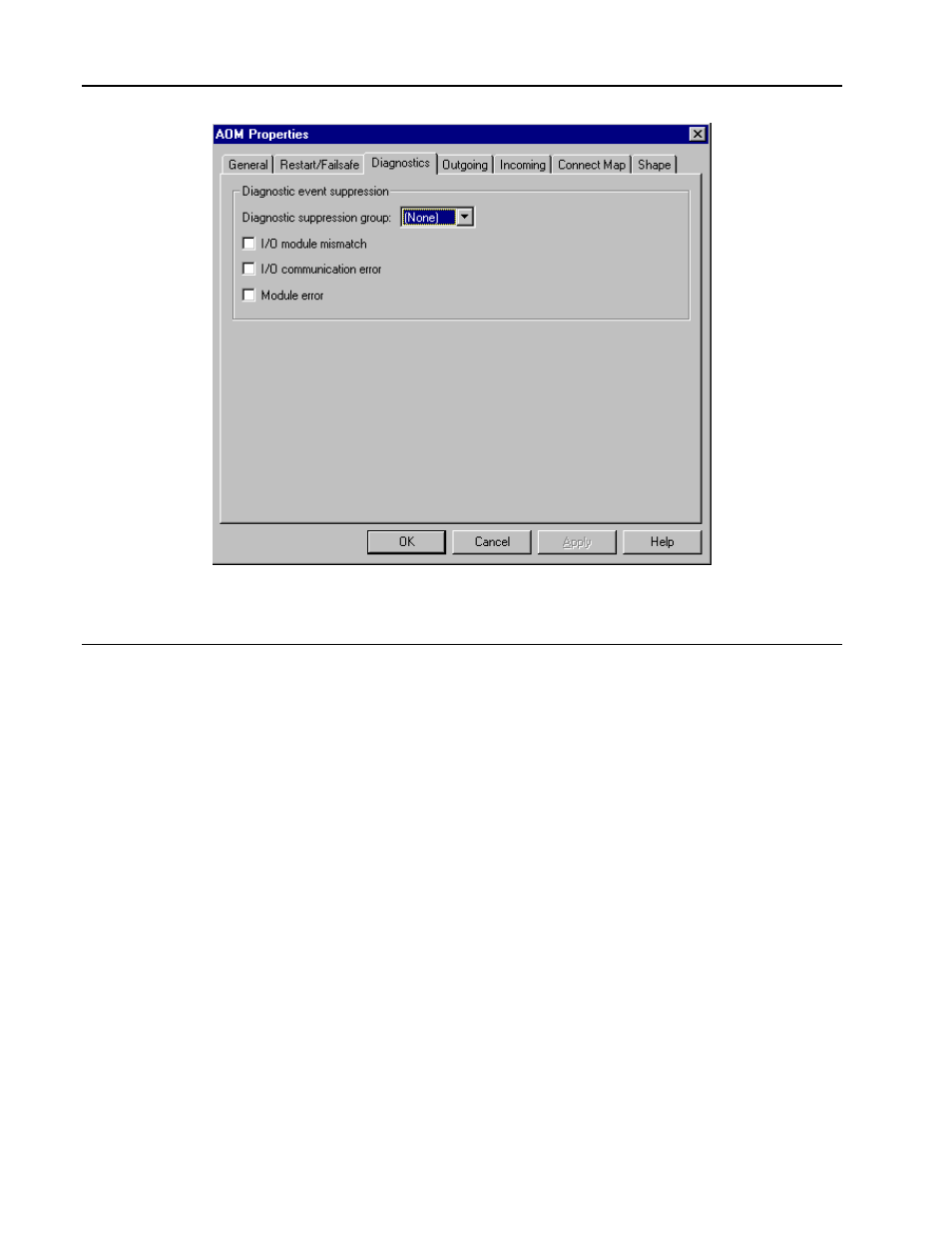
Figure 5-30. Analog Output Module (AOM), Diagnostic Menu
5.5.1
Analog Output Module Block Capabilities
The Analog Output Module block is a data repository for the instrument. One module block
services one module. All values are buffered in one of five possible task state tables. Process
output routines use these tables to pass data between the analog output module blocks, which
are updated every 150 milliseconds for the board, and the process algorithm blocks which run
at the configured scan group interval.
For outputs, all valid data for a single instrument (all 32 analog output module locations) is
written, read, compared and stored in the blocks in a three phased scan cycle (see Figure 5-
12 in Section 5.4). The input connected to the module block is scaled and latched according
to the parameters found the analog output module block’s configuration. This data is then
sent to the output module on the next scan cycle.
Analog output blocks can generate diagnostic errors based upon the following possible
conditions:
•
I/0 mismatch
•
AO module communications error
•
AO module error (used to determine when to get readback and extended error code)
The analog output module handles the digital to analog conversion of an input 2 byte count
value to a milliamp output signal. The signal range of the output module is 0 to 25 milliamps.
The output milliamp signal values for input count values are: 25 mA = 31250 (131.25% of
range), 20 mA = 25000 (100%), 4 mA = 5000 (0%), 0 mA = 0 (-25%). The floating point value
range for a 4 to 20 mA output is (25000 - 5000 = 20000), which provides between 14 and 15
bit resolution over this range or 8
µ
A/Cnt.