Micromod MOD: 1800P - MOD 30ML Identity Module (Version 2) System, I/O and Communications Functions User Manual
Page 133
Logic Functions - Book 1
DIGITAL OUTPUT MODULE BLOCKS (DOM, DDOM, WDOM)
5-13
5.3.2
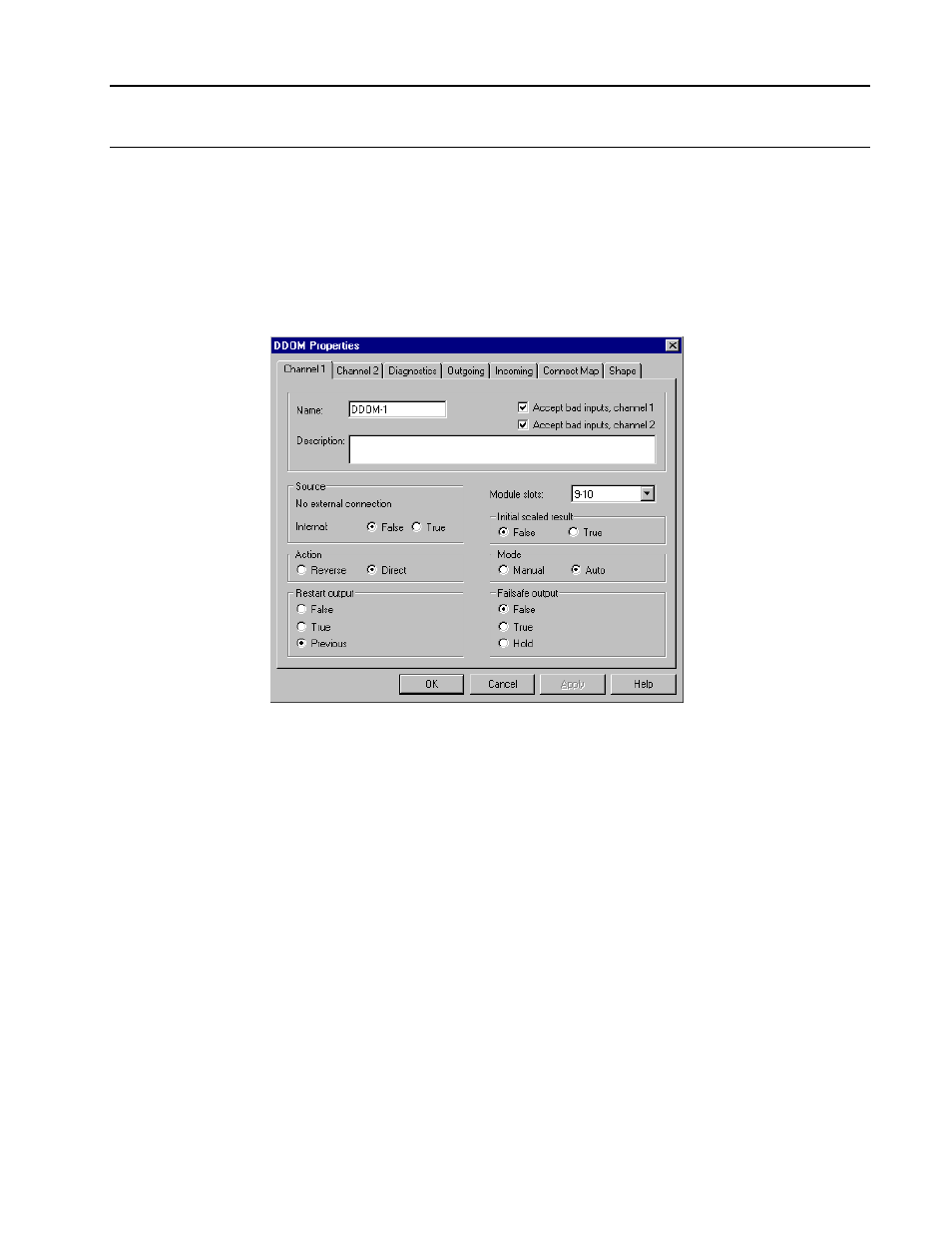
Dual Digital Output Module Block Description (DDOM)
The channel 1 display used to configure the dual digital output module block is shown in
Figure 5-8 and the diagnostic properties display in Figure 5-9.
The mnemonics, valid values,
and data types for all fields that may be selected for display and/or be used in making
softwiring connections are listed in Table 5-3.
NOTE: Channel 1 is the higher numbered module slot position and Channel 2 is the lower
numbered module slot position. For example, Channel 1 is associated with slot 6
when a DDOM module is located in slots 5 and 6. The configuration menus are
otherwise identical.
Figure 5-8. Dual Digital Output Module (DDOM), Channel 1 Configuration Menu