ABUS FU9001 Privest Wireless Alarm Base Set Installation User Manual
Page 21
5-21
5.7 What are the effects of the different jumper settings?
The PC board of the ABUS wireless alarm system is fitted with internal jumpers. Configure the jumpers according to the function
required as shown in this table:
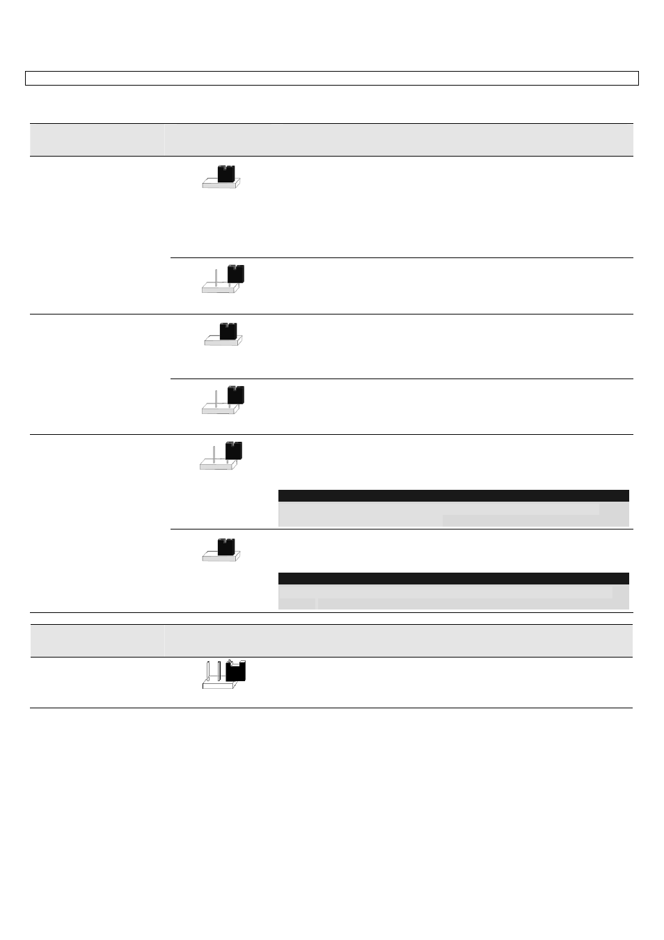
Jumpers on the
mainboard
Position
Function
Restores the factory
settings.
(J9)
The J9 jumper of the ABUS wireless alarm system is used for restoring the
default factory settings of your alarm system.
To restore the factory settings, plug the jumper plug on to both pins of the
jumper. Switch off all electricity to the system and wait at least 10 seconds.
Reconnect the power supply. The factory settings are restored. You can then
take off the jumper plug and plug it on to one pin.
IMPORTANT: Restoring the factory settings is possible only if it was
enabled in the installer menu.
(Default)
The default position of the jumper plug
Rechargeable battery
(J10)
Jumper J10 of the ABUS wireless alarm system is used for selecting
between rechargeable batteries and normal batteries. If the jumper plug is
plugged on to both pins, the batteries are recharged.
IMPORTANT: As this is not the factory settings, this jumper position
must be changed.
(Default)
Use this setting for batteries that cannot be recharged.
Battery protection
(J6)
Jumper J6 of the ABUS wireless alarm system activates/deactivates the
battery discharge protection. If the jumper plug is placed on to one pin, your
alarm system switches off automatically if the battery voltage falls below 6.3V
DC to avoid excess discharge.
NOTE:
With this setting, your alarm system first starts to operate when power is
available from the power supply unit.
(Default)
The battery discharge protection is deactivated, i.e., the battery can
be completely discharged if there is a mains power failure, so that
the batteries have to be replaced.
NOTE:
With this setting, alarm system first starts to operate when the batteries are
inserted.
Jumpers on the
base plate
Position
Function
UO 1 (J5)
or
UO 2 (J5)
(Default)
Defines the function of switch output 1 and switch output 2, as described in
the section “wired utility outputs” on page 5-17.
Default: 1 pin