ABUS BW8060 Wall_ceiling mount User Manual
Deutsch english français, Fig. 1 fig. 2 fig. 4 fig. 3
5INPLBW8060
Deutsch
English
FRANÇAIS
Installationsanleitung Wand-/Deckenhalter
Installation guid
e wall/ceiling swivel
Instru
ctions d’installation du sup
port de Mont
age
Vorbemerkung
Bitte lesen Sie die Bedienungsanleitun
g vor der In
stallation
sorgfältig
durch. Diese ist eine Ergänzung zu
der Anleitung der XEVOX-Bewegungs-
me
lder. Mittels dieser Halterungen kö
nnen Sie Ihre Melder vielfältig
positionieren und ausric
hten. Der Geht
est sollte - wie in der Bedienungs-
anleitung Ihres Melders be
schrieben
- erst nach der vollständigen
Installation mit der entsprechenden
Halterung vorgenom
me
n werden, da
jene einen Ei
nfluss auf
den
Er
fassungsbereich des Mel
ders hat.
Zubehör der Wand- u
nd Deckenhalter
- Wandhalter (Fig. 2) mit Eckenadapter (Fig. 4)
- Deckenha
lter (Fig. 3)
- Schrauben
1. Schritt:
Montage
Entfernen Sie die Platine aus dem
Melderunterteil. Bohren Sie die
Gehäusedurchbrüche Nr. 1 (ØA = 10m
m)
und Nr. 2
auf (Fig. 1).
Wand und Deckemo
ntag
e
Position
ier
en Sie den gewählten Me
lder an dem gewünschte
n Ort und
markieren Sie die Befestigungslöc
her
für die beiden Schrauben. Bohren
Sie die Löcher in die Wand
(Fig. 2)
bzw. Decke (Fig. 3
) und versehen Sie
diese m
it Dübel
n.
Eckmontage:
Positio
nieren Sie den Eck-Adapter (Fig. 4) an dem
gewünsc
hten Or
t und mar
kier
en Sie die
Befestigungslöcher für die beiden
Schrauben. Bohren Sie die Löcher
und stecken Sie dort entsprechende
Dübel hi
nein. Führen Sie das Kabel
durch die große Hauptöffnung in Fig.
4 und befestigen Sie den Eckadapter
mit zwei langen
Schrauben an der
Wand.
Stecken Sie das Kabel durch den Kabelk
ana
l in die Ha
lterung. Befestigen
Sie die Halterung entweder m
it der Wand/Decke über
zwei lange
Schrauben (Positio
n B in Fi
g. 2 und Fig. 3) oder über
zwei kurze
Schrauben mit de
m Ecke
na
dapter. Bit
te vermeiden Sie
Beschädigungen,
wenn Sie die untere Schraube für di
e Wandbefestigung, bzw. die dem
Melder am
nächsten liegende Schr
aube für die Deckenbefestigung,
anziehe
n. Hierzu stehe
n Ihnen spezie
lle L
öcher in der
Anschl
ussplatte
(Position F i
n Fig. 2 und Fi
g. 3) der Halterung zum A
nziehe
n der
Schrauben zur Verfügung.
Wenn der
Kabel entlang de
r Wand bzw. Decke
geführt wird, sollte dieser d
urch die
oberen Gehäusedurchbrüche an den
Rändern der Halterung, in das Meldergehäuse gesteckt werden.
Nehm
en Sie die Melderunt
erseite (P
osition E in Fig. 2
und Fig. 3) und
verschrauben Sie diese m
it dem
Halt
er. Verwenden Sie hierzu die beiden
im
Lieferum
fang befindli
chen, ku
rzen Me
lderbefestigungssc
hrauben
(Position D i
n Fig. 2 und Fi
g. 3).
Führen Sie das Kabel durch den Gehäus
edurchbruch N
r.1 (Fig. 1)
. Richten
Sie den Melder in die gewünschte
Po
sition aus und zie
hen Sie die
Befestigungsschraube der Halterung du
rch die Öffnun
g an. Befestigen Sie
die Melderplatine wieder im
Gehä
useunterteil. Verbinden Sie die
einzelne
n Leitu
ngen m
it den Klem
men (
beachten Sie
bitte hier
zu die
Bedienungsanleitung des X
EVOX-Melders).
2. Schritt: Test
Wenn die Pos
ition des Mel
ders nicht ko
rrekt ist, entfernen Sie bitte noch
einmal die Melderplati
ne, lösen Sie die Befestigungssc
hraube der
Halterung und richte
n Sie den Melder
neu aus. Abschließend m
üssen Sie
die Schraube wieder anziehen. Versehen Sie den Melder wieder mi
t der Frontabdeckung und führen Sie
entsprechend der Bedienungsanleitun
g des X
EVOX
-Me
lder
s einen Gehtest
dur
ch. Der
Melder
kann
nu
n ver
wendet wer
den.
Maximale Winkeleinstellungen Horizontal:
±45
0
Vertical: +6
0
-17.5
0
Achtung: Diese Halterun
gen sind nicht für den XE
VOX PET und
XEVO
X PET MW geeignet.
Before beginning
Please read all the instructi
on carefully
before beginning the installatio
n.
These instructions are m
ea
nt to su
pplem
ent tho
se provided with the
detector. This accessory provides you
with an extra deg
ree of
freedom
in
the positioni
ng and aligni
ng of the
detector.
However
the swivel does
affect the det
ector’s covera
ge pattern
and so the walk test described in the
installation i
nstructio
ns of the de
tector should be perfo
rmed after
installation w
ith the swivel.
The wall/corner/ceilin
g mount accessory
- wall swivel (Fig. 2) with corner adapter
(Fig. 4)
- ceiling swivel (Fig. 3)
- screws
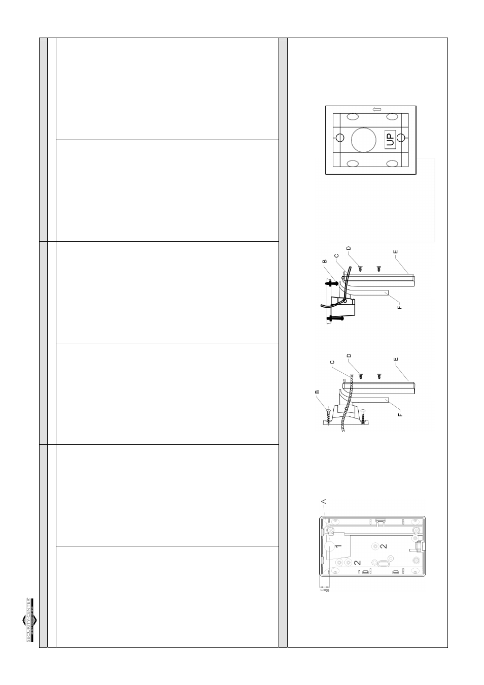
Step 1: Assembly
Remove the printed circu
it from the base
. Drill thr
ough the base
holes/knockout no. 1 (ØA = 10m
m)
and no. 2 (see Fig. 1)
For wall and ceiling appl
ications:
Positio
n the swiv
el at the desired
locations and
mark the dril
ling loca
tion
s for the two screws. Drill these
two holes into the wall (Fig
. 2) or ceiling (Fig. 3) and
insert plastic
anchors.
For Corner applications: Po
sition the co
rner adaptor (Fig. 4) at the desired
location and
mark the drilli
ng locati
ons for the two screws. Drill these two
holes and insert plastic anc
hors. Ru
n the cable throug
h the large central
hole in Fig. 4 and attach the corner
adapter to
the wall with the two log
screws.
Feed the cable through the
cable channe
l in the swive
l. Connect the swivel
either to the wall/ceiling wi
th two lo
ng screws (Positio
n B in Fig. 2 and
Fig. 3) or to the corner ada
pter with
two short screws. Care should be
taken to prevent dam
age to the swiv
el when i
nserting
the lower screw
(wall mounti
ng) or the screw closest to the detector (c
eiling mo
unti
ng).
The two holes i
n the mo
unt
ing plate (Position F i
n Fig.
2 and Fig. 3)
allows easier access for tightening
. If the cable is laid
along the
wall/ceili
ng, it should enter
the sw
ivel through one of the knockouts
provided in the rim
of the u
ppermost edge of the swive
l.
Attach the detector base (P
osition E in
Fi
g. 2 and Fig. 3) and tighten the
two detector mounting scre
ws whic
h hold the swivel, s
ee Position D i
n Fig.
2 and Fig. 3.
Feed the cable through the
knockout
no. 1 (Fig. 1) and tighten the
swivels lock
ing screw after the requir
ed position is achieved. Use the
knockout for this as well. Replace th
e printed circuit board into the base.
Connect the cable wires to the detector
terminal block
as described in the
detector’s installation instr
uctions (XEVOX).
Step 2: Testing
If the position of the detect
or is no
t correct please remove the PCB, loose
the screw and change the p
osition
of the detector. Then tighten the
locki
ng screw again.
Replace the front cover. Per
form
the walk
test as described in the detector
installation i
nstructio
ns. T
he detector is now ready
for
use.
Maximum degree of adj
ustment
:
Horizontal:
±45
0
Vertical: +6
0
-17.5
0
Note: These swivels can
not be used with XEVOX
PET and XEVOX
PET M
W
.
Avant de commencer
Veuillez lire attentivement
toutes le
s instructio
ns avan
t de commen
cer
l’installation. Ces i
nstructio
ns sont
destinées à co
mplé
ter celles qui vous
ont été fournies avec le dét
ecteur. Cet accessoire vous donne une
ma
rge
suppléme
ntaire de manoue
vre dans le po
sitionne
ment
et l’alignement du
détecteur.
Le pivot exercent toutefois
une influe
nce sur le cha
mp
de couverture du
détecteur, le test de
passage à pied décrit dans le mode d’installation du
détecteur, ne doit être
eff
ectué qu’après avoir monté ce dernier avec le
pivot.
Accessoires du suppor
t du mur et
de toit
- Support du mur (Schema.2) avec
adapta
teur de coin (Schema.4)
- support de toit (Schema.3)
- vis
Etape 1
: Montage
Éloignez la carte du circ
uit
intégré du détecteur.
Creuser les perfo
rations Nr
.1 (ØA = 10m
m)
et N
r.2
(schém
a 2)
Montag
e sur l
es murs e
t l
es toi
ts
Placez le pivot à l’endroit voulu et marquez les poi
nts
de perçage de deux
vis. Percez ces deux trous dans le mu
r (Sche
ma.2) ou le toit (Schem
a.3)
et introduisez les chevil
les
en plastique.
Applications
en coin
Placet l’adaptateur d’angle (Schema.4)
à l’endroit vo
ulu et marquez les
points de perçage des deux
vis. Perces ces deux trous dans le mur et
introduisez les c
hevilles en
plastique. Faites passer le câble à travers le
gros trou du milieu et fixes l’adaptat
eur d’angle au mur avec les deux
longues vis à tête plate.
Enfilez le câble à travers la
gaine prévue à cet ef
fet da
ns le pivot. Fixez le
pivot à adaptateur en coin à l’aide de
s vis (Position B du schéma .2 ou
du sché
ma 3)
ou
av
ec le
s v
is
courtes et avec pr
écautions pour éviter de
l’aimer en introduisa
nt la vis inférieure.
Nous vous prions d’éviter les endommagements, qua
nd vous retirez la vis
Du support du mur. Po
ur cela vous disposez des perforations convenable
s
(Position F du schém
a .2 o
u du sché
ma 3).
Si le câble de liaison est fixé sur le
mur ou sur le toit, veuillez utili
ser les
perforations du support po
ur passer le câble au boîtier du détecteur.
Fixez la base du détecteur
et serrez le
s trois vis courtes qui le raccordent
au pivot (Position F du schém
a .2 ou du sché
ma 3).
Faites passer le câble à tra
vers la pe
rfo
ration Nr.1
(Fig2). Installez le
détecteur dans la position s
ouhaitée, et
serrez la vis de
fixation à trave
rs
la perforation.
Replacez la plaque du ci
rcu
it imprimé sur la base.
Branchez les fils d
u
câble au bloc terminal du
dé
tecteur en suivant les instr
uctions du
mode
d’installation de ce dernier
Etape 2
: Test
Si la pos
ition du détecteur n’
est pas
correcte, veuillez retirer la
carte du circuit imprimé,
desse
rrer la vis de fixation, placer le
détecteu
r dans la positio
n souhaitée, fixer la vis
de fixation et
ens
uit replacez la carte du circuit imprimé.
Replacez le couvercle frontal. Effectuez le test de
passag
e à pied
se
lon les
ins
tructions
détaillées
da
ns le mode d’i
nstallation du
détecteu
r. Le détect
eur e
st maintenan
t prêt à l’e
m
ploi.
Degré maximum de réglage :
Horizontal:
±45
0
Vertical: +6
0
-17.5
0
Remarque : le support n’est adap
té p
our les détecte
urs suivan
ts :
XEVO
X PET et XEVO
X PET M
W
.
Fig. 1
Fig. 2
Fig. 4
Fig. 3