ABUS FU9001 Privest Wireless Alarm Base Set Installation User Manual
Page 17
5-17
5.2.3 Fixing the faceplate
Before fixing the faceplate, first read the following sections (up to page 5-20) and then return here. The preceding sections are
not needed for every installation.
When carrying out the following, make sure that the voltage is disconnected for all connection work. Both the power adapter
and the standby batteries must be disconnected.
Before fixing the faceplate, the following installation work should be complete.
• Telephone and power are connected to the PCB of the base plate (section 5.3).
• All connection work for additional control cables is completed on the PCB of the base plate (section 5.5).
• The brightness is adjusted (section 5.4).
• All jumpers are plugged in according to the desired function (section 5.7).
When all these jobs are completed, replace the faceplate and screw it tight. Proceed as follows:
• Connect the flat cable of the faceplate to the base plate.
• Insert the temper spring into the casing for the tamper opening and clip the faceplate from above into the base plate.
• Fold the faceplate down until it clicks audibly into the base plate.
• Screw the case together from below using the screw provided.
The ABUS wireless alarm system is now ready for the following installation steps described in chapter 6.
5.3 How do I install the power and telephone connections?
The ABUS wireless alarm system is powered by a 230V AC power adapter with 9V AC. In this step, make sure only the secondary
power adapter plug is plugged into the base plate (see number 5 on page 5-14: What is what inside the ABUS wireless alarm
system?). The power adapter plug must never be plugged into the mains socket. The socket for the power adapter is on the PCB in
the base plate.
Alternatively, the power adapter plug can be connected directly to the base plate after the plug has been removed. The polarity is
unimportant.
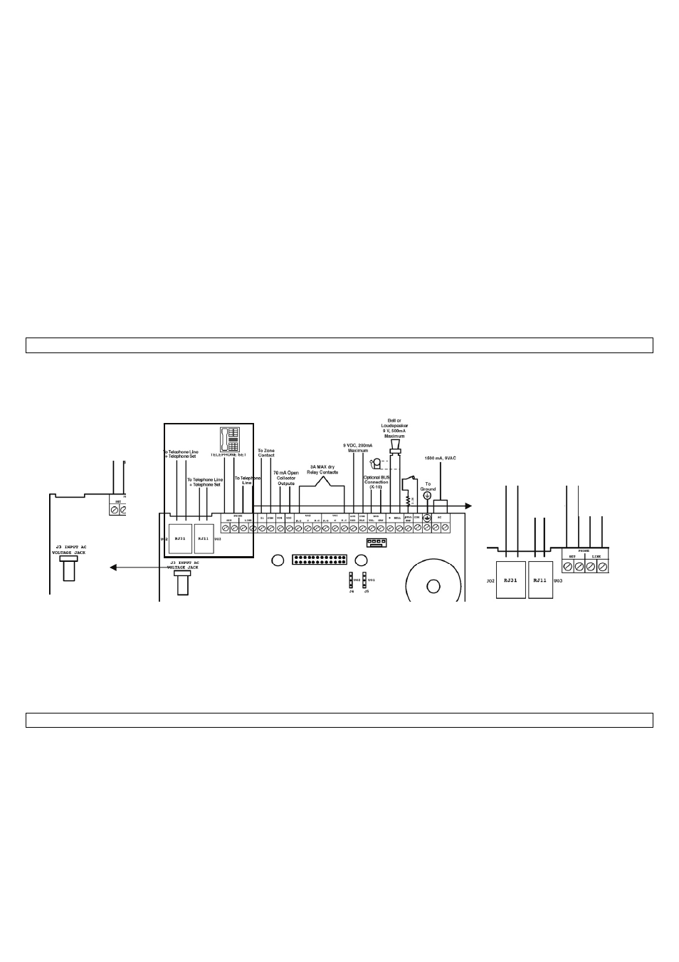
For the telephone connection, you can use either an RJ45 plug or an RJ11 plug. The two analogue telephone cables a and b can
also be connected to the screw clamp as shown in the graphic. Here too, the polarity is unimportant. One or more telephone
terminal devices can be connected, but they must be connected after the ABUS wireless alarm system. The reason: In the event
of an alarm, the system separates the connection to any series-connected telephone terminal devices and then uses this telephone
connection exclusively for transmitting the alarm message (blockade switching). In this way, you prevent a “busy” telephone from
blocking the line in the event of an alarm. To connect your telephone terminal devices to the system, see the above sketch. The
cables of your telephone line must be connected to the Line connector of the ABUS wireless alarm system. Connect the cables of
your telephone or PBX to the Set connector.
5.4 How do I adjust the contrast of the LCD display?
The ABUS wireless alarm system has a dimmer for adjusting the brightness and contrast of the LCD display. You should make
adjustments after plugging into the power supply and before replacing the faceplate on the base plate.
To make this setting, turn the LCD light dimmer (see number 8 on page 5-14: What is what inside the ABUS wireless alarm system?)
carefully with a small flat screwdriver until you have set the right brightness.
9 V AC connector
RJ31
Line/Set
RJ11
Line/Set
Screw
terminal
a/b Set
Screw
terminal
a/b Line