Toshiba e-Studio Imaging 6520c User Manual
Page 98
e-STUDIO5520C/6520C/6530C
© 2008 TOSHIBA TEC CORPORATION All rights reserved
2-64
2. Copier-specific Adjustments
Procedures
* You can start with any of the procedures. But it is recommended to perform the procedures in order, as listed
below. You can use one procedure in conjunction with another. But if this changes the image quality more
than required or loses the effectiveness of the adjustment, restore the settings made in the previously used
procedure to the original ones. Then use other procedures.
* Both the service technician and the user can use procedure (1).
* Only the service technician must use procedure (2).
(1) Change the threshold for the Auto Color mode.
• Follow steps (a) through (d) to perform the adjustment.
(a) Press the [USER FUNCTIONS] tab on the Control Panel to enter the "User Functions" menu.
(b) Press the [USER] button.
(c) Press the [COPY] button.
(d) Change the threshold with the "ACS ADJUSTMENT" indicator. If you move the indicator to the left,
the original tends to be judged as a black original. If you move it to the right, the original tends to be
judged as a color original.
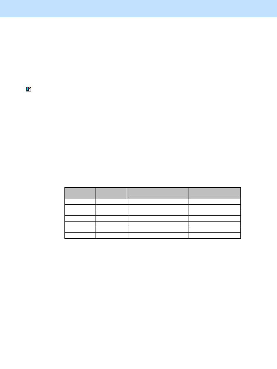
The relation between the position of the "ACS ADJUSTMENT" indicator and the judgment
result is shown below. In the actual adjustment, the threshold varies depending on the shape and
size of the original or the density level of the original image. Therefore use the table below only
as a reference.
Position of
indicator
Adjustment
value
No. of stamps
No. of red characters
0
+230
Approx. 10 judged as color
Approx. 100
1
+190
Approx. 5 judged as color
Approx. 60
2
+150
Approx. 3 judged as color
Approx. 40
3
+90
Approx. 2 judged as color
Approx. 20
4
+40
Approx. 1 judged as color
Approx. 10
5
0
Approx. 1/2 judged as color
Approx. 6
6
-20
Approx. 1/2 judged as black
4 or more
* Position of indicator: "0" in the table above denotes the left end of the indicator (the original is
judged as black most) and "6" denotes the right end of the indicator (the original is judged as
color most).
* Adjustment value: This refers to the judgment threshold for the Auto Color mode. The
adjustment value of the code in step (2) below will be added to this value.
* The diameter of the standard "stamp" is approx. from 8 mm to 12 mm. In this field the number
of the stamps on the chart and its judgment result are described.
* The size of the standard "red character" is approx. 10.5 pt. In this field the number of the red
characters entered and its judgment result are described.
After specifying the original size and copy size, copy and check the copy image quality.
If further image quality adjustments are still necessary, the service technician must use the next procedure.