External paging system, Connecting the paging system – Nortel Networks BCM1000 User Manual
Page 228
228
Chapter 14 Installing optional telephony equipment
P0607659 02
External paging system
(customer supplied)
You can connect an external paging system to provide paging over external loudspeakers.
Ensure the paging system follows these guidelines:
•
The paging output from the MSC is 100 mV rms across an input impedance of 600
Ω.
•
The output level is 0 dBm with reference to 600
Ω, for a PCM encoded signal at 0 dBm. There
is no dc voltage across the page output terminals.
•
The page output uses the tip and ring terminals of the jack. The sleeve terminal of the jack
connects to ground. You must use a stereo plug to connect the page signal output.
When you use the page signal output jack to connect an external paging amplifier, you also use the
page relay jack which contains a floating relay contact pair. The system uses this jack to control
the external paging amplifier.
•
The contact pair has a switch capacity of 50 mA (non-inductive) at 40 V (maximum). You
must remove any inductive load on the output.
•
The page relay contacts connect to the tip and ring terminals of the jack. The sleeve terminal of
the jack connects to ground. You must use a stereo plug to connect the page relay.
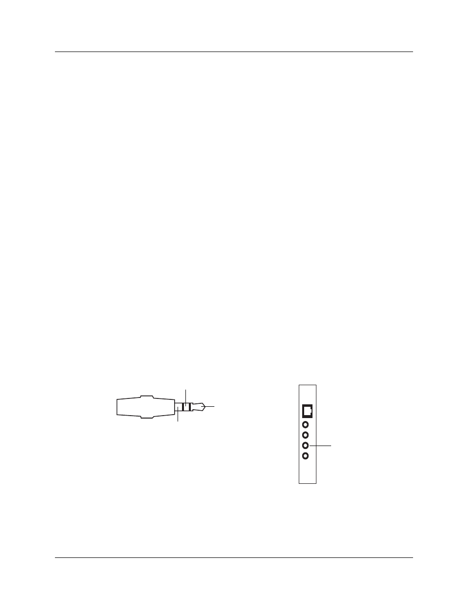
Connecting the paging system
Install the external paging system using the installation instructions that came with the paging
system.
1
Connect the paging system audio input to the Page output on the MSC. Refer to
Figure 92
Audio input jack
Audio input jack
MSC faceplate
Tip
:
Page signal
Ring
:
Page signal
Sleeve
: Ground
Tip
Ring
Sleeve
Page output