Nortel Networks BCM1000 User Manual
Page 20
20 BCM1000, BCM 3.5 addendum
BCM1000 Installation and Maintenance Guide
P0607659 02
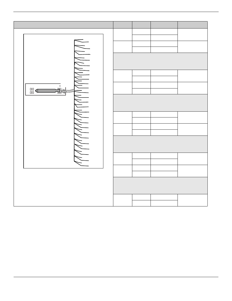
The following figure and table show the wiring pin outs for a GATM to connect to a service provider.
Connector pinout
Line
Pin
Wire color
GATM module
1
26
White-Blue
Both
1
Blue-White
2
27
White-Orange Both
2
Orange-White
No
connectio
n
28/3
29/4
3
30
White-Slate
Both
5
Slate-White
4
31
Red-Blue
Both
6
Blue-Red
No
connectio
n
32/7
33/8
5
34
Red-Brown
GATM8
9
Brown-Red
6
35
Red-Slate
GATM8
10
Slate-Red
No
connectio
n
36/11
37/12
7
38
Black-Green
GATM8
13
Green-Black
8
39
Black-Brown
GATM8
14
Brown-Black
No
connectio
n
40/15 to
49/24
Aux
50
Violet-Slate
Both
25
Slate-Violet
* Auxiliary port function: In download mode, the auxiliary port function for all profiles operates as a true Auxiliary
port. This means that when the power comes back on, and if the Aux Port is in-use, that line will show on the
system telephones as being in-use (LCD indicator lit) until the Aux Call is cleared.
In dipswitch mode, the North American and Taiwan auxiliary ports also act as true auxiliary ports.
However, the UK and Australia profile auxiliary port function is different. In these profiles, when the power is
restored, the Aux Port call is terminated and the line is available to system telephones.
8R
7R
6R
5R
4R
3R
2R
1 R
9R
10R
11R
12R
13R
14R
15R
16R
33T
32T
31T
30T
29T
28T
27T
26 T
34T
35T
36T
37T
38T
39T
40T
41T
17R
42T
18R
43T
19R
44T
20R
45T
21R
46T
22R
47T
23R
48T
24R
49T
25R
50T
*AUX
Line 1
Line 2
Line 3
Line 4
Line 5
Line 6
Line 7
Line 8