Analog transmission parameters, Figure 85 – Nortel Networks BCM1000 User Manual
Page 218
218
Chapter 13 Installing Analog Terminal Adapters
P0607659 02
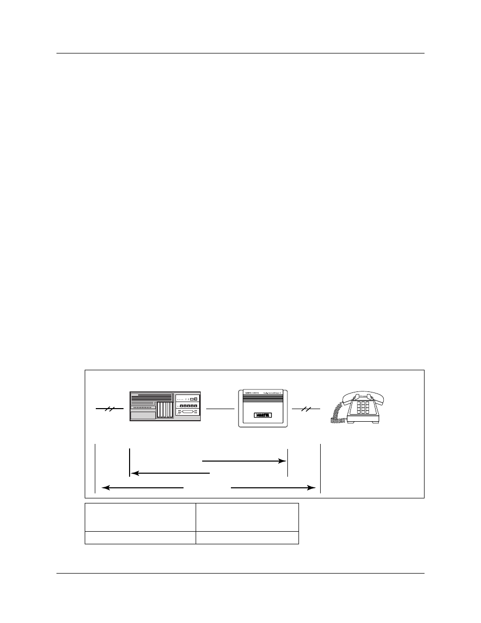
Analog transmission parameters
(North American systems only)
The following are the required analog parameters for an ATA2:
The maximum loss for ATA 2 to Central Office (CO) configuration, shown in
, must not
exceed 10 dB.
Figure 85
Insertion loss from the CO to the single-line telephone
ATA 2 to Business Communications Manager
system loop resistance (cable only)
135 ohms maximum (for example: 800 m of
0.5 mm wire or 2,600 ft. of 24 AWG wire)
Analog loop resistance on terminal side for
voice applications (cable only)
1,300 ohms maximum (for example: 4,600 m of
0.4 mm wire or 15,000 ft. of 26 AWG wire)
Analog loop resistance on terminal for data
applications (cable only)
200 ohms maximum (for example: 730 m of
0.4 mm wire side or 2,400 ft. of 26 AWG wire)
Input impedance at tip and ring
600 ohms
Return loss
> 20 dB for 200 to 3,400 Hz (when Network terminated
with 600 ohms)
Insertion loss on an internal call
ATA 2 to Business Communications Manager system loss
3.0 dB ± 0.5 dB
Insertion loss on an external call
ATA 2 to Business Communications Manager system loss
2.2 dB ± 1.0 dB
Business Communications Manager system to ATA 2 loss
0.5 dB ± 1.0 dB
Longitudinal balance to ground
50 dB
60 to 4,000 Hz
With IEEE 455-1976 test
Overload level
3 dB
Single-line telephone
ATA 2
BCM1000
Business Communications Manager to ATA 2
ATA 2 to Business Communications Manager
10 dB Max
Cable loss
Central Office
cable loss