Wire serial i/o mode operation – NEC PD75402A User Manual
Page 95
84
CHAPTER 5. PERIPHERAL HARDWARE FUNCTIONS
Serial clock selection bit (W)
The P01/SCK pin status depends on the CSIM1 setting as shown below.
CSIM1
P01/SCK Pin Status
0
High impedance
1
High level
The following procedure should be used to clear CSIE during a serial transfer.
➀
Clear the interrupt enable flag (IECSI) to set the interrupt disabled state.
➁
Clear CSIE.
➂
Clear the interrupt request flag (IRQCSI).
5.5.5
3-Wire Serial I/O Mode Operation
The 3-wire serial I/O mode allows connection to the system used in the 75X series,
µ
PD7500 series, 87AD series,
etc.
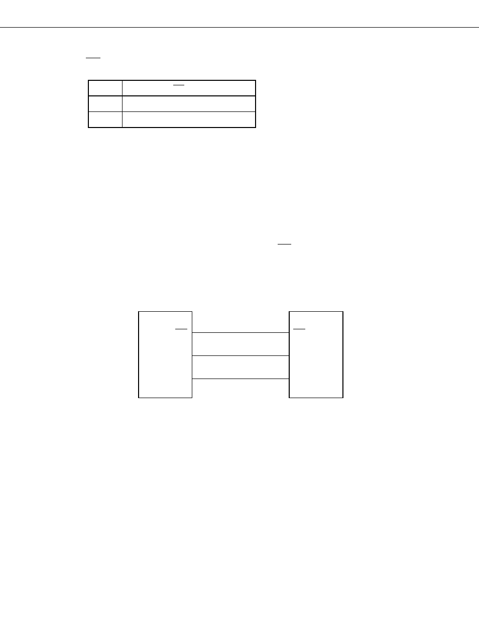
Communication is performed using three lines: The serial clock (SCK), serial output (SO), and serial input (SI).
Fig. 5-28 Example of 3-Wire Serial I/O System Configuration
3-wire serial I/O
↔
3-wire serial I/O
SCK
Master CPU
SO
SI
SCK
SI
SO
Slave CPU
➤
➤
➤
(1)
Register setting
When the device is used in the 3-wire serial I/O mode, setting can be performed by means of the following two
registers:
• Serial operating mode register (CSIM)
• Serial bus interface control register (SBIC)