NEC PD75402A User Manual
Page 119
108
CHAPTER 5. PERIPHERAL HARDWARE FUNCTIONS
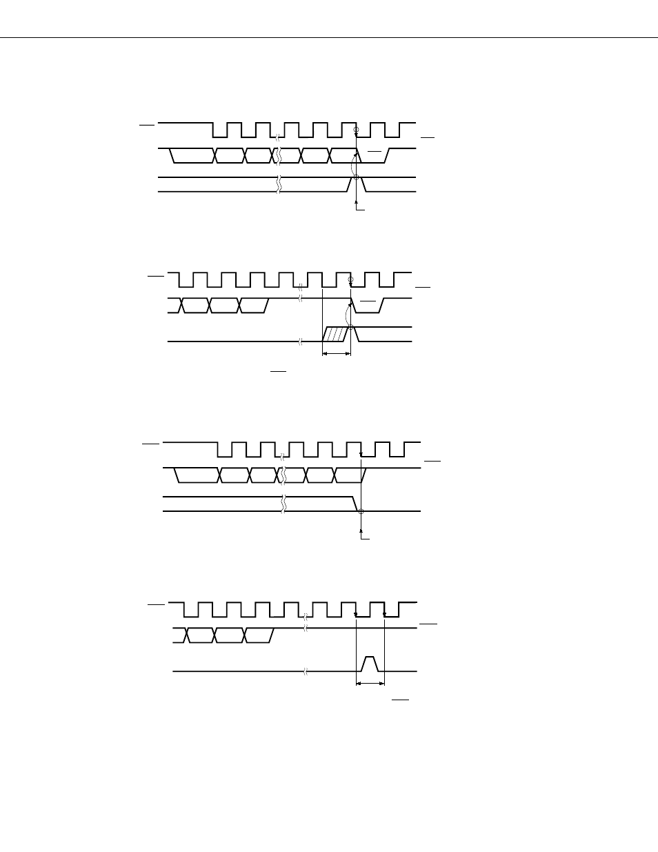
Fig. 5-45 ACKE Operation
(a)
When ACKE = 1 on completion of transfer
(b) When ACKE is set after completion of transfer
SCK
SB0
ACKE
When ACKE = 1 at this point
ACK signal is output in 9th
clock cycle.
1
2
7
8
9
D7
D6
D2
D1
D0
ACK
SCK
SB0
ACKE
When ACKE is set in this interval and ACKE = 1 on
next fall of SCK
ACK signal is output in 1
clock interval immediately
after ACKE is set.
7
8
9
D2
D1
D0
ACK
6
(c)
When ACKE = 0 on completion of transfer
(d) When ACKE = 1 interval is short
SCK
SCK
ACKE
1
2
7
8
9
D7
D6
D2
D1
D0
ACK signal is not output.
When ACKE = 0 at this point
SCK
SB0
ACKE
ACK signal is not output.
When ACKE is set and cleared in this interval and
ACKE = 0 on next fall of SCK
D2
D1
D0
This manual is related to the following products: