Basic intercal timer mode register (btm) – NEC PD75402A User Manual
Page 78
67
CHAPTER 5. PERIPHERAL HARDWARE FUNCTIONS
5.4.2
Basic Intercal Timer Mode Register (BTM)
BTM is a 4-bit register which controls the operation of the basic interval timer.
BTM is set by a 4-bit memory handling instruction. Bit operations are not possible.
Example
To set the interrupt generation interval to 1.95 ms (4.19 MHz).
MOV
A, #1111B
MOV
BTM. A
; BTM
←
1111B
When bit 3 is set (1), the contents of the basic interval timer are cleared and at the same time the basic interval
timer interrupt request flag (IRQBT) is also cleared (start of basic interval timer).
With a RESET input, BTM contents are cleared to zero and the interrupt request signal generation interval is set
to the maximum length.
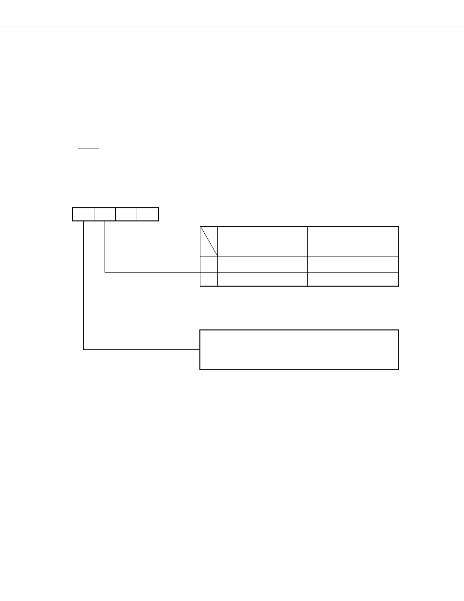
Fig. 5-22 Basic Interval Timer Mode Register Format
Note
Ensure that 1 is written to bits 1 and 0.
3
2
1
0
Symbol
F85H
BTM3 BTM3
1
1
BTM
0
f
XX
/2
9
(8.18 kHz)
2
17
/f
XX
(31.3 ms)
1
f
XX
/2
5
(131 kHz)
2
13
/f
XX
(19.5 ms)
Interrupt Interval
Wait Time when Standby
Mode is Released)
Input Clock Specification
Basic interval timer is started by writeng “1”* (counter
and interrupt request flay are interrupt request flag are
cleared). Automatically reset (0) when operation is started.
Basic interval timer start control bit
( ) : Values when f
XX
= 4.19 MHz
(
)
Address
* Ensure that the write is performed by a 4-bit write instruction.