NEC PD75402A User Manual
Page 141
130
CHAPTER 6. INTERRUPT FUNCTIONS
(2)
External interrupt input pin hardware
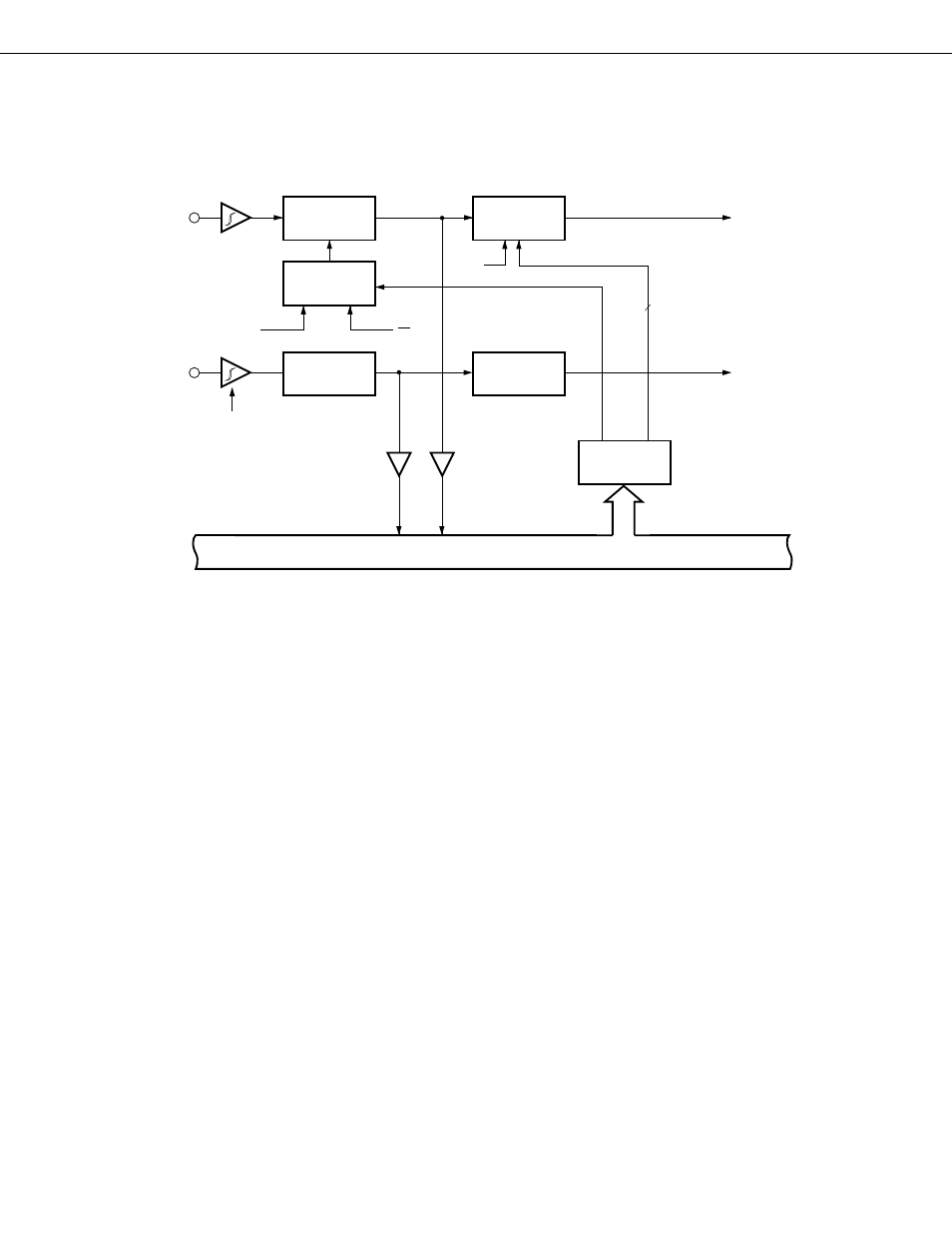
The configuration of INT0 and INT2 is shown in Fig. 6-3.
Fig. 6-3 Configuration of INT0 and INT2
4
IM0
Input
Buffer
Input Buffer
with Hysteresis
Characteristics
Internal Bus
INT2/P12
INT0/P10
Sampling Clock
Noise Elimina-
tion Circuit
Selector
Analog Delay
Noise Elimina-
tion Circuit
Φ
f
xx
64
Edge Detec-
tion Circuit
Rising Edge
Detection
Circuit
Φ
IM01, IM00
IM03
2
INT0
(IRQ0 Setting Signal)
INT2
(IRQ2 Setting Signal)
INT0 functions as an external interrupt input on which sampling clock noise elimination and detected edge
selection can be performed. The INT0 noise elimination circuit detects a change in level in 2 sampling clock pulses.
Therefore, pulses narrower than the width of the 2 cycles (2t
CY
*
or 128/f
XX
) of sampling clock are eliminated as noise,
and a pulse exceeding the width is properly acknowledged as an interrupt signal (see Fig. 6-4). One of 3 clocks can
be selected as the timing clocks.
*
Cycle time