Stack pointer (sp) – NEC PD75402A User Manual
Page 48
CHAPTER 4. INTERNAL CPU FUNCTIONS
37
4.6
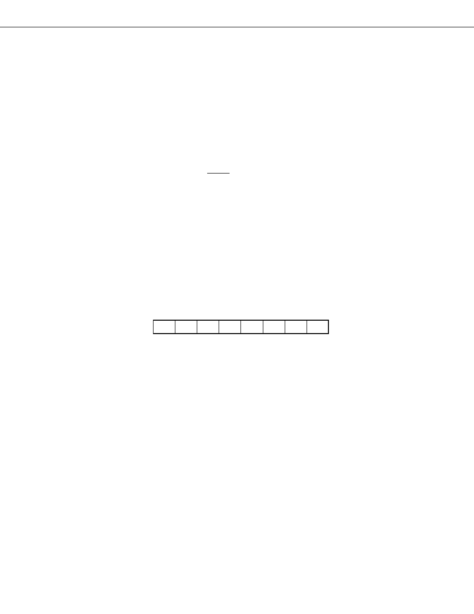
STACK POINTER (SP) ..... 8 BITS
The
µ
PD75402A uses a static RAM as the stack memory (LIFO format). The 8-bit register holding the top address
information of such a stack memory area is the stack pointer (SP). Fig. 4-7 shows its format.
As the SP’s high-order 3 bits are fixed to 001, the stack area is at the static RAM’s addresses 020H to 03FH.
The SP is decremented before write (save) in the stack memory and is incremented after read (restore) from the
stack memory. Figs. 4-8 and 4-9 show the data saved and restored by each stacking operation.
The SP sets the initial value by the 8-bit data transfer instruction to determine the stack area. It is impossible to
read the content of the SP.
Zero is always written in the SP’s bit 0.
It is recommended to initialize by writing 40H in the SP and use the built-in RAM’s maximum address (03FH) and
beyond as the stack area.
The content of the SP turns indeterminate at RESET input, so it must be initialized to your desired value by the
program initialization routine.
Note
The SP of the Evachip packaged on the board for evaluation can address all the areas of 000H to 0FFH unlike
in the
µ
PD75402A. To eliminate such a difference at evaluation, the SP should be set not to access beyond
the range of 020H to 03FH.
Example
SP initialize
MOV
XA, #40H
MOV
SP, XA
; SP
←
40H
Fig. 4-7 Stack Pointer Configuration
Address
7
6
5
4
3
2
1
0
Symbol
F80H
0
0
1
SP4
SP3
SP2
SP1
SP0
SP
↑
0 Fixed