NEC PD75402A User Manual
Page 114
103
CHAPTER 5. PERIPHERAL HARDWARE FUNCTIONS
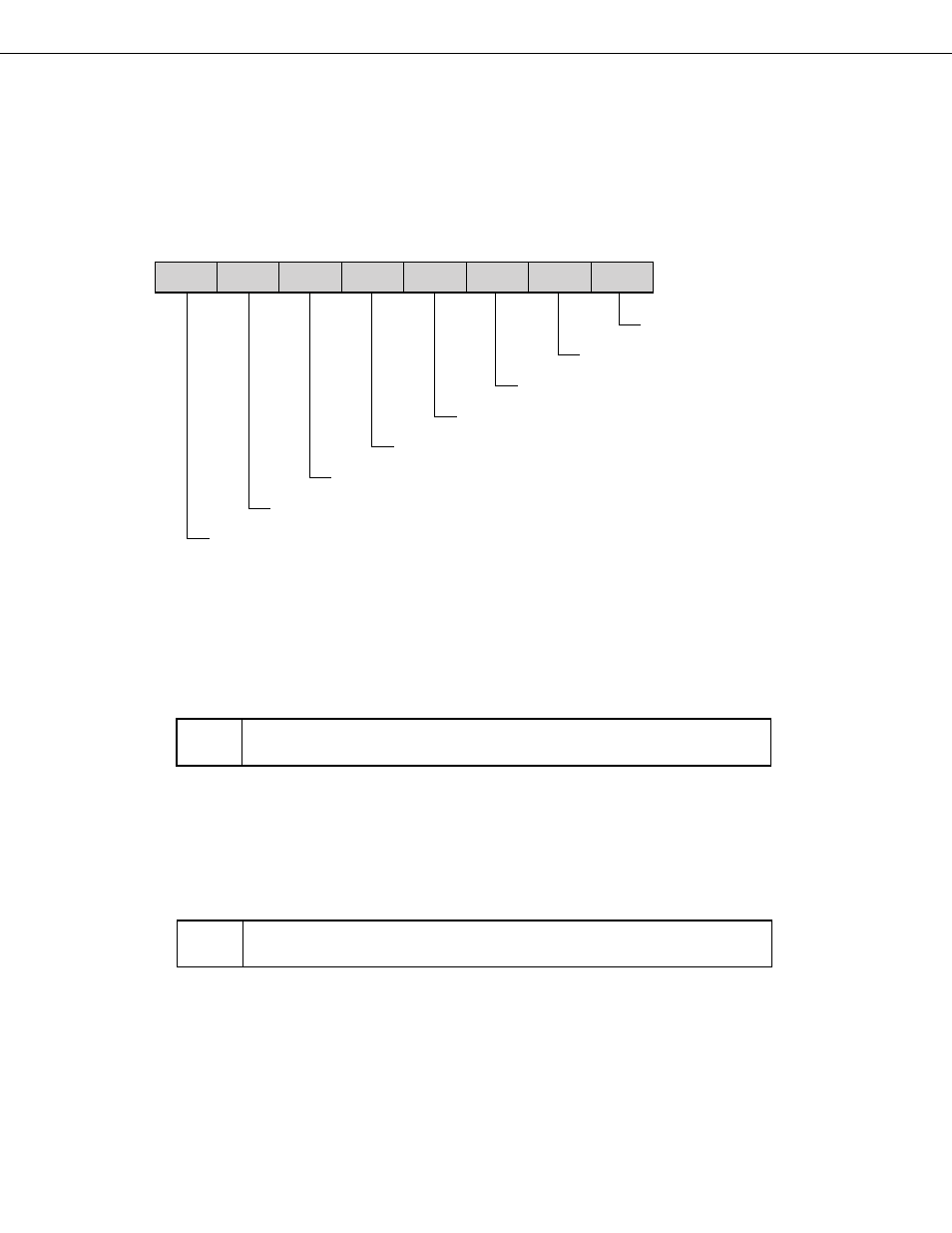
(b) Serial bus interface control register (SBIC)
When the SBI mode is used, SBIC is set as shown below (see 5.5.3 (2) “Serial bus interface control register”
for full details of SBIC).
SBIC is manipulated by bit manipulation instructions.
Reset input clears the SBIC register to 00H.
The shaded area indicates bits used in the SBI mode.
Address
7
6
5
4
3
2
1
0
Symbol
FE2H
BSYE
ACKD
ACKE
ACKT
CMDD
RELD
CMDT
RELT
SBIC
Bus Release Trigger Bit (W)
Command Trigger Bit (W)
Bus Release Datection Flag (R)
Command Detection Flag (R)
Acknowledge Trigger Bit (W)
Acknowledge Enable Bit (R/W)
Acknowledge Detection Flag (R)
Busy Enable Bit (R/W)
Remarks
(R)
Read only
(W)
Write only
(R/W) Read/write enabled
Bus release trigger bit (W)
RELT
The bus release signal (REL) trigger output control bit. The SO latch is set (1) by setting this
bit (RELT = 1), after which the RELT bit is automatically cleared (0).
Note
SB0 must not be set during a serial transfer: Ensure that it is set before a transfer is started or after it is
completed.
Command trigger bit (W)
CMDT
The command signal (CMD) trigger output control bit. The SO latch is cleared (0) by setting
this bit (CMDT = 1), after which the CMDT bit is automatically cleared (0).
Note
SB0 must not be set during a serial transfer: Ensure that it is set before a transfer is started or after it is
completed.